Oil and gas mixed damper

An oil-gas mixing and damper technology, which is applied to gas-liquid shock absorbers, shock absorbers, shock absorbers, etc., can solve the problem that automatic return cannot be realized, and achieve the effect of easy return and convenient operation.

Inactive Publication Date: 2012-10-03
江苏亚希维医疗器械有限责任公司
View PDF5 Cites 0 Cited by
  • Summary
  • Abstract
  • Description
  • Claims
  • Application Information

AI Technical Summary

Problems solved by technology

[0002] At present, there are various forms of damping products, but all of them are only for the purpose of damping, and cannot realize automatic return. Therefore, it is necessary to add other return devices during use to achieve the effect of use.

Method used


Image

  • Oil and gas mixed damper

Examples


Embodiment Construction

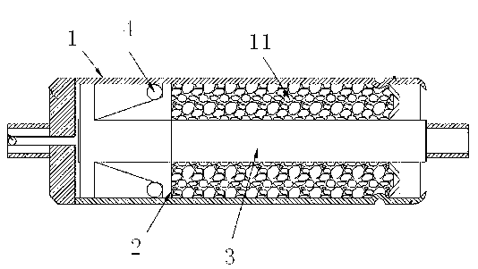
[0010] An oil-gas mixing damper according to the present invention comprises a pipe body 1, a hydraulic oil 11 is arranged in the pipe body, a piston 2 and a piston rod 3 are arranged in the pipe body 1, and one end of the piston rod 3 is connected to the piston 2, The other end protrudes out of the pipe body 1; the bottom end of the piston 2 is a 45-degree oblique groove structure, and flow holes are arranged on the front and rear end faces of the piston 2, and the diameter of the flow hole at the rear end of the piston is larger than that at the front end of the piston. An O-ring 4 is arranged in the oblique groove at the rear end of the piston 2 .

[0011] When in use, the front end of the piston is a small flow hole. When the force is compressed inward, the O-ring moves upwards according to the movement track, and closes with the upper end of the oblique angle at the rear end of the piston and the inner wall of the tube, so that when the oil is discharged, it will The over...


PUM


Abstract

The invention discloses an oil and gas mixed damper which comprises a pipe body. Hydraulic oil is arranged in the pipe body; a piston and a piston rod are arranged in the pipe body; one end of the piston rod is connected with the piston, and the other end of the piston rod extends out of the pipe body; the rear end of the piston is of a bevel groove structure; flow holes are arranged in the front and rear end surfaces of the piston; and an O-shaped ring is arranged in the bevel groove structure in the rear end of the piston. During the use, the oil and gas mixed damper not only can play a damping role, but also can easily return, and is convenient to operate.

Description

technical field [0001] The invention relates to a damper, in particular to an oil-air mixing damper. Background technique [0002] At present, there are various types of damping products, but all of them are solely for the purpose of damping, and cannot realize automatic return. Therefore, other return devices need to be added during use to achieve the use effect. Contents of the invention [0003] In order to overcome the problems existing in the prior art, the purpose of the present invention is to provide an oil-air mixing damper, which can play a damping role during use, and can be easily returned to its position and is easy to operate. [0004] The purpose of the present invention is achieved through the following technical solutions: [0005] An oil-gas mixing damper, comprising a pipe body in which hydraulic oil is arranged, is characterized in that: a piston and a piston rod are arranged in the pipe body, one end of the piston rod is connected with the piston, ...

Claims


Application Information

Patent Timeline
Patent Type & Authority Applications(China)
IPC IPC(8): F16F9/06F16F9/32
Inventor 尹向阳
Owner 江苏亚希维医疗器械有限责任公司
Why Eureka
Try Eureka