Supercharge Your Innovation With Domain-Expert AI Agents!

RFID (radio frequency identification device) antenna detection device and application thereof

An antenna detection and equipment technology, which is applied in the field of radio frequency identification tag detection, can solve the problems of reducing real-time detection, losing reference standards, and limited antenna forms, etc., and achieves the effects of fast efficiency, avoiding deviation, and strong adaptability

Active Publication Date: 2012-10-03
HUAZHONG UNIV OF SCI & TECH
View PDF4 Cites 14 Cited by
  • Summary
  • Abstract
  • Description
  • Claims
  • Application Information

AI Technical Summary

Problems solved by technology

[0008] The disadvantage of existing software detection equipment is that it is time-consuming to achieve high detection accuracy, which reduces the real-time performance of detection
In addition, when the device does not communicate with the terminal, it cannot be detected. When all antennas of the device are abnormal, it cannot be detected due to the loss of reference standards. This method is applicable to limited types of antennas.

Method used


Image

  • RFID (radio frequency identification device) antenna detection device and application thereof
  • RFID (radio frequency identification device) antenna detection device and application thereof
  • RFID (radio frequency identification device) antenna detection device and application thereof

Examples


Embodiment Construction

[0039] The present invention is described now in conjunction with the preferred implementation examples of the accompanying drawings.

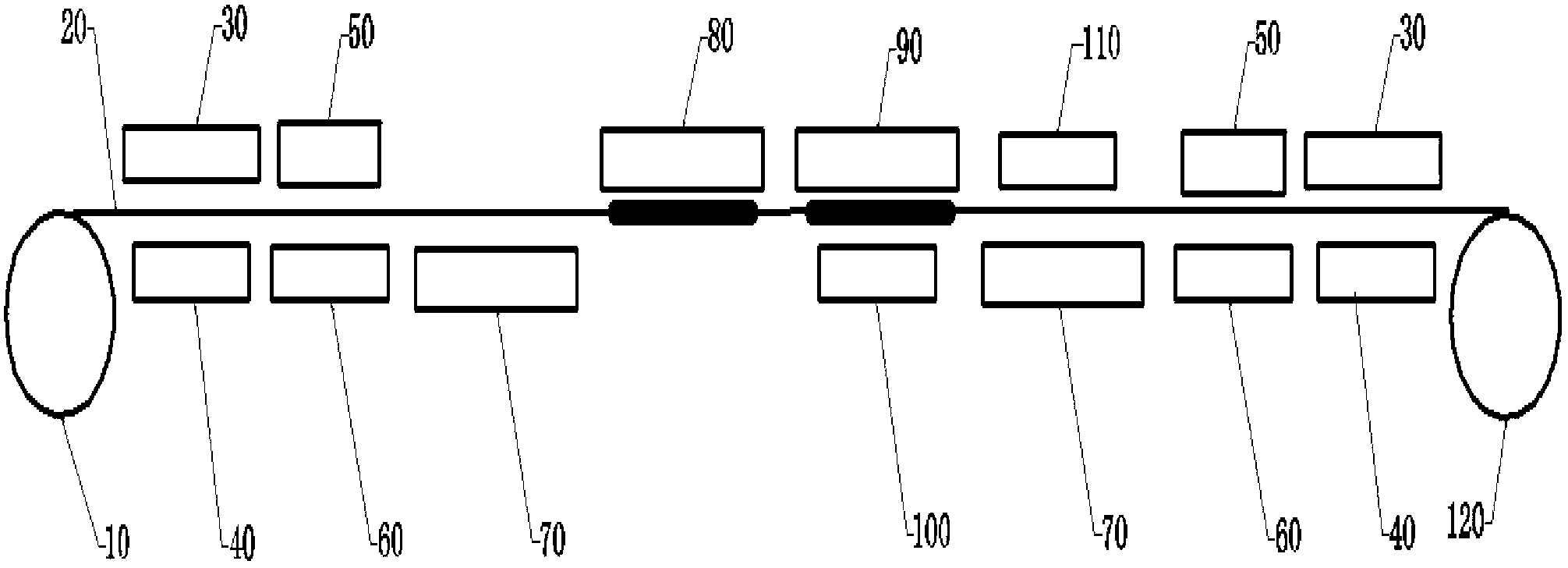
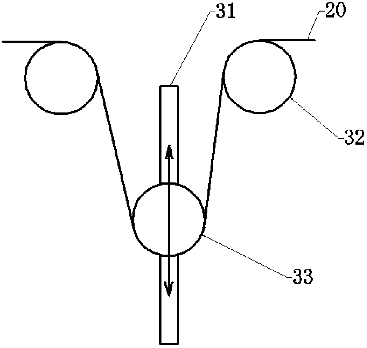
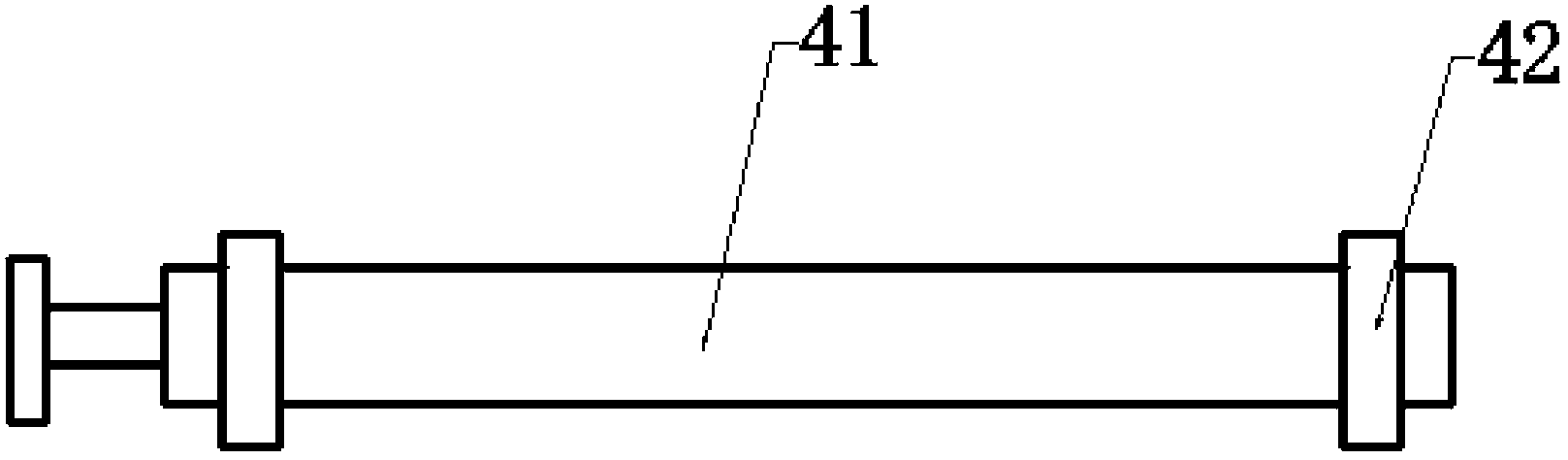
[0040] see figure 1 , a preferred embodiment of the present invention mainly includes an uncoiling device 10, a tension control device 30, a deviation correction device 40, a material receiving device 50, a static clamping assembly 60, a vacuum adsorption assembly 70, an appearance detection device 80, a resistance detection device 90, a printing The marking device 100, the moving clamping assembly 110, and the winding device 120 jointly complete the detection of the printed or etched antenna on the antenna substrate 20.

[0041] Among them, the static clamping assembly 60 and the dynamic clamping assembly 110 constitute a conveying device, and the two sets of vacuum adsorption assemblies 70 constitute a vacuum adsorption device. The unwinding device 10 wraps around the antenna substrate 20 and is located at the front end of the device. An R...


PUM


Abstract

The invention provides an antenna detection device which is used for detecting an RFID (radio frequency identification device) antenna and comprises a decoiling device, a coiling device, a static clamping assembly, a vacuum absorption assembly, an appearance detection device, a resistance detection device and a dynamic clamping assembly; the static clamping assembly, the vacuum absorption assembly, the appearance detection device, the resistance detection device and the dynamic clamping assembly are sequentially arranged between the decoiling device and the coiling device; an antenna substrate decoiled by the decoiling device is conveyed to the detection position through the dynamic clamping assembly; the static clamping assembly clamps the antenna substrate after the dynamic clamping assembly loosens the antenna substrate; the antenna substrate is adsorbed on a detection support panel by the vacuum absorption assembly and then is respectively detected by the appearance detection device and the resistance detection device; and after the detection, the coiling device recoils the detected antenna substrate. The invention also discloses steps for utilizing the antenna detection device to perform RFID antenna detection. According to the invention, the antenna detection device can detect overall dimension of the RFID antenna and defects including conglutination, burr, disconnection, sand holes and the like. Besides, the antenna detection device has high precision, high efficiency and strong adaptability and can detect RFID antennas with different types and different dimensions.

Description

technical field [0001] The invention belongs to the field of radio frequency identification tag detection, and in particular relates to an RFID antenna detection device and a process method thereof. Background technique [0002] Radio Frequency Identification (RFID) is a non-contact automatic identification technology. RFID tags have the advantages of waterproof and antimagnetic, large storage capacity, long service life, strong anti-interference ability, long distance and high degree of intelligence that barcodes do not have. They are widely used in logistics, commodity tracking, manufacturing process control, supply chain management, and retail systems. , automatic payment system and other fields have broad application prospects. [0003] The RFID tag is composed of a tag antenna and a tag chip package. As a device that receives and emits electromagnetic waves, the tag antenna is a key component in a wireless communication system. The performance of the RFID system larg...

Claims


Application Information

Patent Timeline
Patent Type & Authority Applications(China)
IPC IPC(8): G01N21/88G01R27/02
Inventor 陈建魁尹周平尹庆吉苏刚周春雷钟强龙杨航吉羽
Owner HUAZHONG UNIV OF SCI & TECH
Features
  • R&D
  • Intellectual Property
  • Life Sciences
  • Materials
  • Tech Scout
  • Unparalleled Data Quality
  • Higher Quality Content
  • 60% Fewer Hallucinations
Learn More