Method for repairing pixel bright spot

A bright spot and pixel technology, which is applied in the field of repairing pixel bright spots, can solve the problems of long processing time and low repair efficiency of pixel bright spots, and achieve the effect of fast repair speed, low cost of repair equipment, and simple repair methods

Inactive Publication Date: 2012-10-03
BOE TECH GRP CO LTD +1
View PDF3 Cites 4 Cited by
  • Summary
  • Abstract
  • Description
  • Claims
  • Application Information

AI Technical Summary

Problems solved by technology

[0006] However, when the above-mentioned BM covering method and CF carbonization method are used to repair pixel bright spots, the actual production needs to be processed step by step, resulting in a long processing time, which reduces the repair efficiency of pixel bright spots

Method used


Image

  • Method for repairing pixel bright spot
  • Method for repairing pixel bright spot
  • Method for repairing pixel bright spot

Examples


Embodiment Construction

[0028] In order to make the purpose, technical solutions and advantages of the embodiments of the present invention clearer, the embodiments of the present invention will be further described in detail below in conjunction with the embodiments and the accompanying drawings. Here, the exemplary embodiments and descriptions of the present invention are used to explain the present invention, but not to limit the present invention.

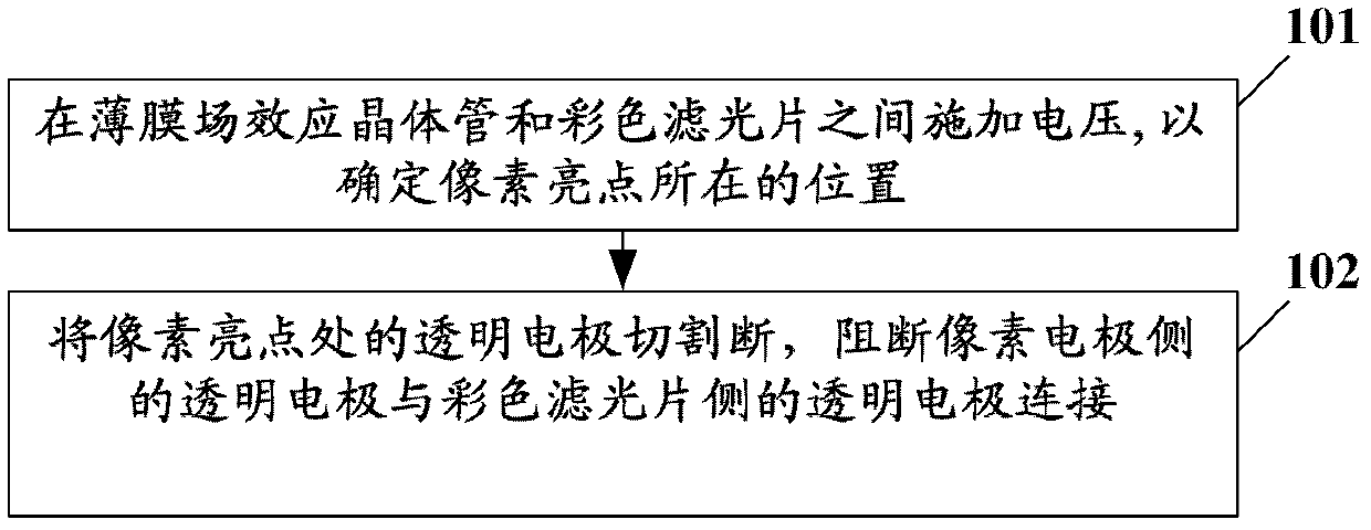
[0029] Such as figure 1 As shown, it is a flowchart of a method for repairing pixel bright spots in an embodiment of the present invention, and the specific steps are as follows:

[0030] Step 101, applying a voltage between the thin film field effect transistor and the color filter to determine the position of the bright spot of the pixel;

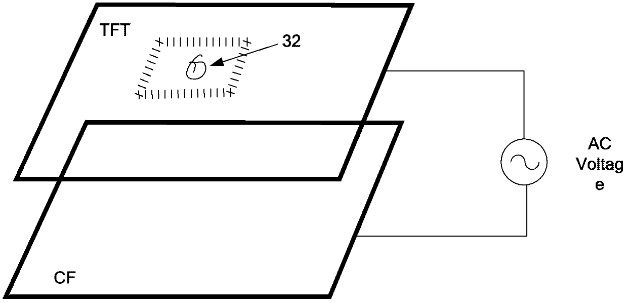
[0031] Such as figure 2 As shown, by applying a voltage (AC Voltage) between the thin film field effect transistor (TFT) and the color filter (CF), the liquid crystal molecules in the liquid crystal panel are ...


PUM


Abstract

The invention provides a method for repairing a pixel bright spot. The method comprises the following steps of: cutting off a transparent electrode at the pixel bright spot; and cutting connection between a transparent electrode on a pixel electrode side and a transparent electrode on a color filter side. The method for repairing the pixel bright spot is simple; and the efficiency for repairing the pixel bright spot can be effectively improved.

Description

technical field [0001] The invention relates to a liquid crystal panel (TFT-LCD) repair technology, in particular to a method for repairing pixel bright spots applied in the liquid crystal panel. Background technique [0002] During the manufacture of the liquid crystal panel, foreign matter including dust, organic matter, metal, etc. will be absorbed into the liquid crystal panel. When foreign objects are attracted to areas close to certain color filters, the pixels corresponding to these color filters will emit light much brighter than the brightness of the rest of the normal pixels, which is called pixel bright spots. [0003] Existing technologies for repairing pixel bright spots caused by foreign matter mainly include: BM covering method and CF carbonization method, among which [0004] The BM (black matrix) covering method mainly uses laser to form a gap at the color filter with pixel bright spots or between the color filter and the glass substrate, and uses laser dec...

Claims


Application Information

Patent Timeline
Patent Type & Authority Applications(China)
IPC IPC(8): G02F1/13G02F1/1362
Inventor 吴涛范朋张钟石
Owner BOE TECH GRP CO LTD
Why Eureka
Try Eureka