
Method and system for de-noising touch detection device

A technology of touch detection and noise reduction processing, applied in the direction of electrical digital data processing, input/output process of data processing, instruments, etc., can solve problems such as increased weight, increased system cost, and decreased product yield, so as to weaken the influence, The effect of reducing product cost

Active Publication Date: 2012-10-03
SHENZHEN GOODIX TECH CO LTD
View PDF4 Cites 34 Cited by
  • Summary
  • Abstract
  • Description
  • Claims
  • Application Information

AI Technical Summary

Problems solved by technology

[0015] Another structure in which the driving electrodes 13 and the sensing electrodes 15 are alternately arranged on the same plane is as Figure 6A and 6B As shown, at this time, the driving electrodes 13 cannot be closely arranged to cover the sensing electrodes 15, and cannot function as a shielding layer. Therefore, an additional conductive shielding layer 24 needs to be added in this way.
[0016] These structural methods have several disadvantages: 1. Increase the difficulty of the sensor manufacturing process, reduce the yield rate of the product, and increase the cost; 2. Increase the thickness of the sensor, thereby increasing the weight and reducing the light transmittance; 3. This method can only shield the interference signal from the bottom of the sensor, such as the interference from the LCD display, but it cannot resist other interference signals, such as power ripple interference and radio frequency interference.
But this method will complicate the structure of the touch sensor, and it will also take up more touch controller detection ports, which will obviously increase the cost of the system

Method used


Image

  • Method and system for de-noising touch detection device
  • Method and system for de-noising touch detection device
  • Method and system for de-noising touch detection device

Examples


Embodiment Construction

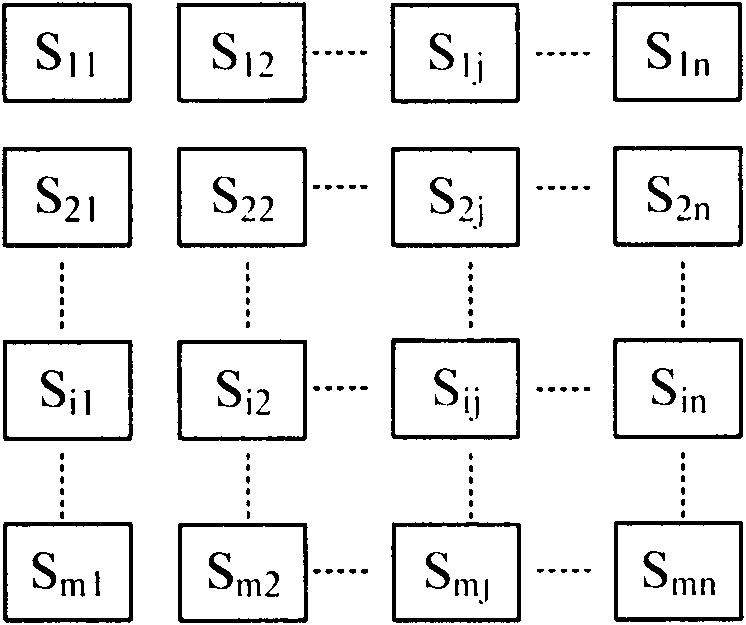
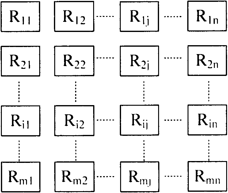
[0054] In order to make the object, technical solution and advantages of the present invention clearer, the present invention will be further described in detail below in conjunction with the accompanying drawings and embodiments. It should be understood that the specific embodiments described here are only used to explain the present invention, not to limit the present invention.

[0055] In the embodiment of the present invention, the touch detection nodes are divided into several groups (such as one group for each row, or one group for each column, or a combination of several rows and columns), and synchronous sampling is performed for each group, so that each group of sampling data is affected by interference signals. The impact is also the same or close to the same. The sampling value of the same group of detection points is affected by the same amplitude and direction of the interference signal, and then the noise component in the sampling data is filtered out as a DC of...


PUM


Abstract

The invention is applicable to the technical field of touch control and provides a method for de-noising a touch detection device. The method comprises the following steps of: (A), synchronously sampling touch detection nodes which belong to the same group, and storing sampling data; (B), respectively comparing the sampling data with corresponding reference values, calculating difference data which serve as detection data, and replacing the original sampling data with the detection data; (C), counting the detection data which are obtained by replacement in the step B, screening effective data according to preset screening conditions, and calculating direct current offset components which represent noise components; and (D), respectively subtracting the direct current offset components which are obtained in the step (C) from the detection data which are obtained by calculation in the step (B), and thus obtaining the de-noised detection data. According to the characteristic that synchronous sampling values of the same group of detection points have the same amplitude and direction under the influence of an interference signal, the noise components in the sampling data serve as the direct current offset components and are filtered, and influence of an external interference signal on the detection performance of the touch detection device is weakened.

Description

technical field [0001] The invention belongs to the field of touch technology, and in particular relates to a detection data noise reduction processing method and system of a touch detection device. Background technique [0002] The touch detection device includes a variety of application forms such as touch buttons, touch panels, and touch screens, and specifically includes various touch detection methods such as infrared, resistive, ultrasonic, inductive, and capacitive. In a typical touch detection device, the touch controller is connected to the touch sensor, collects touch detection data from the sensor, and then processes the detection data to determine the coordinate position of the touch point, specifically as figure 1 shown. [0003] Sampling of the touch sensor is usually carried out in a scanning manner on each detection node. For example, for a capacitive multi-touch screen, the detection node is a plurality of projected capacitive nodes distributed vertically ...

Claims


Application Information

Patent Timeline
IPC IPC(8): G06F3/041G06F3/044
CPCG06F3/0412G06F3/044G06F3/0418G06F3/04182G06F3/0445
Inventor 邓耿淳陈小祥
Owner SHENZHEN GOODIX TECH CO LTD
Learn More