Shift register, grid driving device and display device

A shift register and gate technology, applied in static memory, digital memory information, instruments, etc., can solve problems such as large layout space, unfavorable panel implementation, complex circuit composition, etc., and achieve the effect of shifting

Active Publication Date: 2012-10-03
BOE TECH GRP CO LTD +1
View PDF4 Cites 33 Cited by
  • Summary
  • Abstract
  • Description
  • Claims
  • Application Information

AI Technical Summary

Problems solved by technology

The implementation of a D flip-flop requires 2 transmission gates, an inverter and a NAND gate, and a shift register requires two D flip-flops, so although the traditional shift register is classic, it uses more gates The circuit, the circuit structure is too complicated, and requires a large typesetting space, which is not conducive to the realization of the narrow frame of the panel (panel)

Method used


Image

  • Shift register, grid driving device and display device
  • Shift register, grid driving device and display device
  • Shift register, grid driving device and display device

Examples


Embodiment Construction

[0049] In order to make the object, technical solution and advantages of the present invention more clearly, the present invention will be further described in detail below in conjunction with the accompanying drawings and specific embodiments.

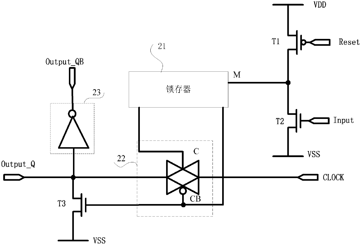
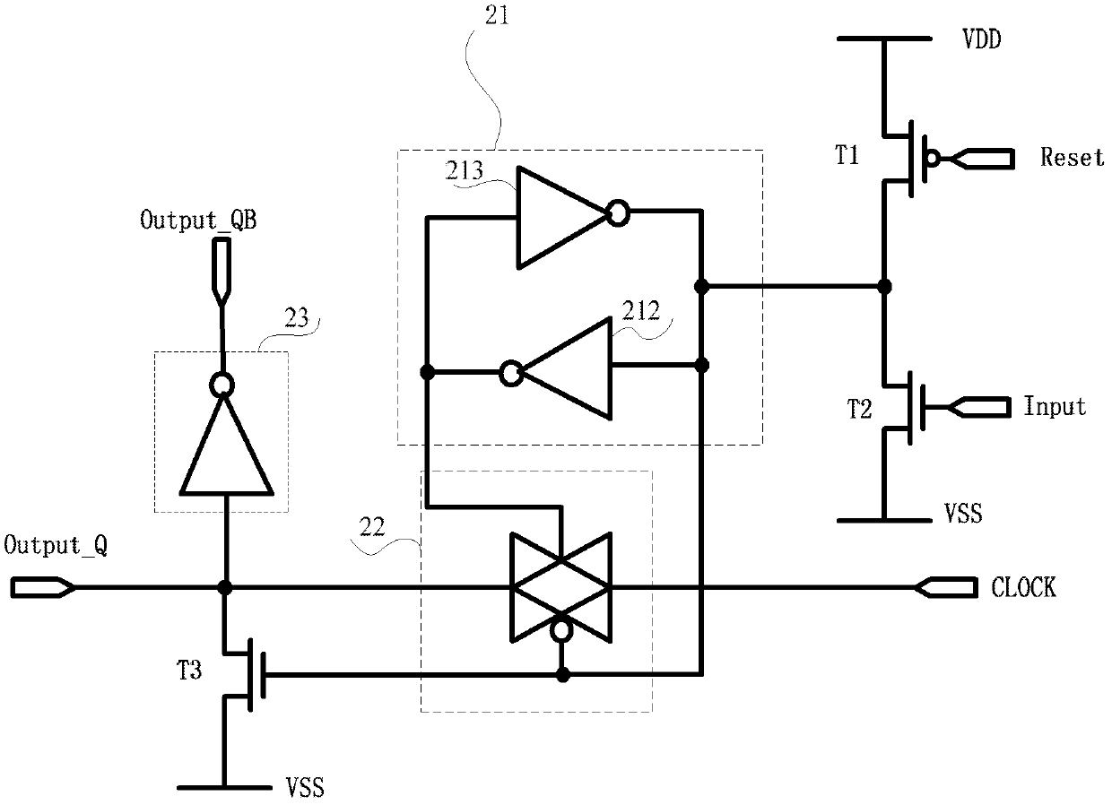
[0050] The invention provides a shift register, a gate drive device and a display device, which can realize signal shift by using only one latch. The shift register of the present invention is mainly composed of a latch and a transmission gate. The latch is used to latch the control signal of the transmission gate so that the transmission gate can be kept on or off. The state of the gate selectively inputs the clock signal to shift the signal.

[0051] Such as figure 2 As shown, the shift register described in the first embodiment of the present invention includes a latch 21, a transmission gate 22, a first thin film transistor T1, a second thin film transistor T2, a third thin film transistor T3 and a first inverter 23 ,in,

[00...


PUM


Abstract

The invention provides a shift register, a grid driving device and a display device. The shift register comprises a latch, a transmission gate, a first thin film transistor, a second thin film transistor, a third thin film transistor and a first inverter, wherein a grid of the first thin film transistor is connected with a reset terminal of the shift register, a drain of the first thin film transistor is respectively connected with a drain of the second thin film transistor and an input terminal of the latch, a grid of the second thin film transistor is connected with an input terminal of theshift register, a grid of the third thin film transistor is connected with an inverted output terminal of the latch, a drain of the third thin film transistor is connected with an input terminal of the first inverter, an output terminal of the transmission gate is connected with the drain of the third thin film transistor, an input terminal of the transmission gate is connected with a clock signal input terminal, the drain of the third thin film transistor is connected with a normal phase output terminal of the shift register, and an output terminal of the first inverter is connected with an inverted output terminal of the shift register. The shift register can realize signal shift by the aid of one latch.

Description

technical field [0001] The present invention relates to the field of display technology, in particular to a shift register, a gate driving device and a display device. Background technique [0002] The traditional LTPS (low temperature polysilicon) shift register (shift register) is composed of an inverter and a transmission gate, and generally has two latches. Use the latch to latch the output signal, and use the switch of the transmission gate to realize the delay and shift of the signal. [0003] figure 1 It is a traditional shift register, mainly composed of two D flip-flops, D is the input terminal, Q is the output terminal, reset is the reset terminal, clk_ and clk are two inverted clock signals, the operation of the traditional shift register The principle is as follows: when the clock turns on the first D flip-flop, the level signal input by the shift register of the upper stage enters the first D flip-flop. Since the transmission gate at the front end of the secon...

Claims


Application Information

Patent Timeline
Patent Type & Authority Applications(China)
IPC IPC(8): G09G3/36G09G3/20
CPCG09G3/3611G09G3/20G11C19/287G11C19/28G09G2310/0286
Inventor 青海刚祁小敬
Owner BOE TECH GRP CO LTD
Why Eureka
Try Eureka