Automatic lamp holder turnover and transportation machine for LED (light-emitting diode) lamp

A technology of turning over a mechanism and a lamp head, which is applied in the mechanical field to achieve the effects of high work efficiency, few operation steps and simple mechanism

Inactive Publication Date: 2015-04-08
MAANSHAN LIANBANG INTELLIGENT EQUIP
View PDF10 Cites 2 Cited by
  • Summary
  • Abstract
  • Description
  • Claims
  • Application Information

AI Technical Summary

Problems solved by technology

[0006] Aiming at the problem existing in the prior art that the 180-degree turning process of the lamp body in the LED lamp assembly line cannot be automated, the present invention provides a lamp head turning mechanism and a lamp head turning and handling machine, which can realize the automation of the lamp body Flip and shift, while the mechanism is simple, low cost, less operation steps, high work efficiency

Method used


Image

  • Automatic lamp holder turnover and transportation machine for LED (light-emitting diode) lamp
  • Automatic lamp holder turnover and transportation machine for LED (light-emitting diode) lamp
  • Automatic lamp holder turnover and transportation machine for LED (light-emitting diode) lamp

Examples


Embodiment 1

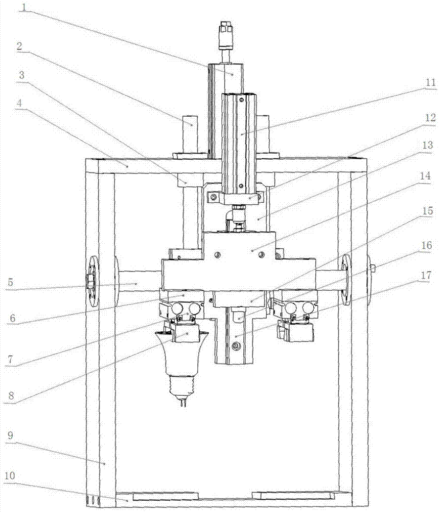
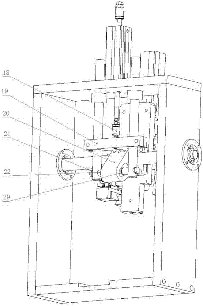
[0035] Such as figure 1 , figure 2 As shown, the turning mechanism includes turning cylinder 1, guide column 2, linear bearing 3, top plate 4, rotating shaft 5, cylinder seat 6, jaw cylinder 7, jaw finger 8, column plate 9, bottom plate 10, upper and lower cylinders 11, Cylinder block 12, panel 13, movable plate 14, linear guide rail 17, movable joint 18, connecting plate 19, swivel seat 20, jump ring 21, rotating shaft 22, needle roller bearing 29.

[0036] Turning cylinder 1 is fixed on top plate 4, and top plate 4 is screwed with two column plates 9. Turning cylinder 1 is connected with connecting plate 9 through movable joint 8. Two linear bearings 3 are fixed on the top plate 4, and two guide posts 2 pass through corresponding linear bearings 3 respectively. The two guide posts 2 pass through the connecting plate 9 arranged horizontally, and the connecting plate 9 and the two guide posts 2 are fixed together. The lower end of the guide post 2 is provided with a throu...

Embodiment 2

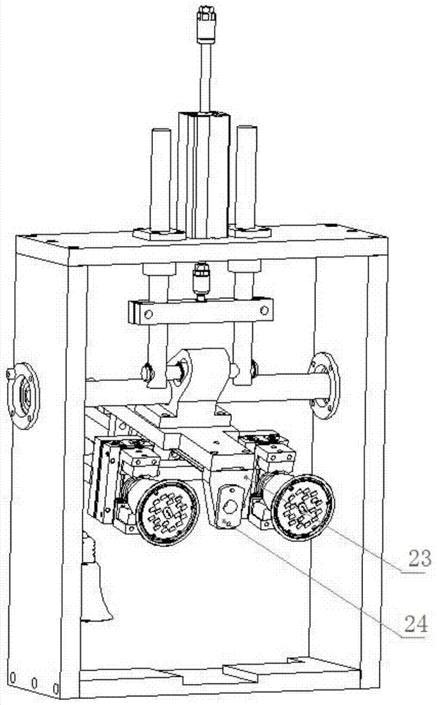
[0040] Such as image 3 As shown, the end of the movable plate 14 can also be fixed with a copper sleeve seat 24, and the copper sleeve seat 24 is fixed with a copper sleeve 23.

Embodiment 3

[0042] Such as Figure 4 As shown, a turning and handling machine is composed of a first turning mechanism 25 and a second turning mechanism 26. The first turning mechanism 25 and the second turning mechanism 26 have basically the same structure and are arranged axially symmetrically. Before turning over, the lamp head of the initial lamp body 27 faces upwards, and after being turned over and transported by the machine of the present invention, the bottom of the turned lamp body 28 faces down, and can move several distances on the same operating table or move from the first operating table to the second operating table. tower.

[0043] Compared with the second turning mechanism 26 of the first turning mechanism 25, the end of the movable plate 14 in the first turning mechanism 25 can also be fixed with a copper sleeve seat 24, and the copper sleeve seat 24 is fixed with a copper sleeve 23. The end of the movable plate 14 in the second turning mechanism 26 is fixed with a plug...


PUM


Abstract

The invention discloses an automatic lamp holder turnover and transpiration machine for an LED (light-emitting diode) lamp, belonging to the mechanical field. The turnover and transpiration machine comprises a first turnover mechanism and a second turnover mechanism which are in mirror symmetry; each turnover mechanism comprises a turnover gas cylinder, a guide pillar, a linear bearing, a top plate, a rotary shaft, a gas cylinder base, a clamping jaw gas cylinder, clamping jaw fingers, a stand column plate, upper and lower gas cylinders, a panel, a movable plate, a movable joint, a connecting plate, a rotary base and a rotary shaft. By adopting a mode of respectively turning over left and right parts by 90 degrees, the automatic lamp holder turnover and transportation machine can be used for realizing the turnover and shifting of the lamp, and can be used for realizing the automation turnover of a lamp body. Meanwhile, the automatic lamp holder turnover and transpiration machine is simple in structure and low in manufacturing cost. A grabbing step and a putting-down step of the lamp body are respectively completed by two turnover mechanisms without mutual interference, so that the working efficiency is high. The clamping jaw fingers in the automatic lamp holder turnover and transpiration machine are simple, and the proper clamping jaw fingers can be designed according to the specific grabbing position of the lamp body.

Description

technical field [0001] The invention relates to the field of machinery, in particular to a transporting machine for flipping lamp caps during lamp assembly. Background technique [0002] Under the economic model dominated by the market economy, in order to adapt to the rapidly changing market requirements, new requirements are put forward for assembly automation. For automated high-speed mechanical assembly, it is necessary to conduct in-depth research on precision assembly technology to adapt to the challenges brought by the development of modern precision machinery to assembly technology. At the same time, it can also greatly increase the product yield and productivity, reduce the production cost of enterprises, and improve the competitiveness of enterprises, which is of great significance to the development of enterprises and industries. [0003] With the development of LED lighting lamps, in order to adapt to the fully automatic production of LED lighting lamps in facto...

Claims


Application Information

Patent Timeline
Patent Type & Authority Applications(China)
IPC IPC(8): B23P19/00
CPCB23P19/007
Inventor 倪明姚路路
Owner MAANSHAN LIANBANG INTELLIGENT EQUIP
Why Eureka
Try Eureka