Driving circuit for display panel

A technology for display panels and driving circuits, applied in static indicators, instruments, etc., can solve the problems of increasing the area, increasing the energy waste of the gamma correction circuit 22, increasing the area and the cost of components, etc., achieving a wide range of applications and improving fast writing. The effect of entering data

Inactive Publication Date: 2012-10-03
CPTF VISUAL DISPLAY (FUZHOU) LTD +1
View PDF4 Cites 0 Cited by
  • Summary
  • Abstract
  • Description
  • Claims
  • Application Information

AI Technical Summary

Problems solved by technology

Therefore, gamma correction circuit 22 increases energy waste and increases area
[0004] In addition, as shown in Figure 1, the two energy transfer switches of the booster circuit 21 must be used in the form of external transistors in order to have the ability to withstand high voltage, which also increases the area and component cost

Method used


Image

  • Driving circuit for display panel
  • Driving circuit for display panel
  • Driving circuit for display panel

Examples


Embodiment Construction

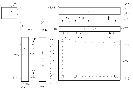
[0071]Please refer to FIG. 2 . FIG. 2 is a schematic diagram illustrating a display panel driving circuit 300 according to an embodiment of the present invention, wherein the display panel 202 can be a cholesteric liquid crystal display panel. However, the present invention is not limited to the display panel 202 being a cholesteric liquid crystal display panel. The driving circuit 300 includes a single inductor dual voltage generator 302 , a first multiplexer 304 , a multiple voltage generator 306 and a second multiplexer 308 . The single inductor dual voltage generator 302 has an inductor 3022, and the single inductor dual voltage generator 302 is used to generate and output a positive voltage VP and a negative voltage VN according to an input voltage VIN and the inductor 3022; the first multiplexer 304 It is coupled to the single-inductance dual-voltage generator 302, and is used to sequentially drive and couple to the liquid crystal display according to the positive voltag...


PUM


Abstract

A driving circuit for a display panel comprises a single-inductor double-voltage generator, a first multiplexer, a multi-voltage generator and a second multiplexer, wherein the single-inductor double-voltage generator generates and outputs a positive voltage and a negative voltage according to an input voltage and an inductor; the first multiplexer sequentially drives a plurality of scanning lines of the display panel according to the positive voltage, the negative voltage, input data and a first clock pulse generated by a clock pulse generator; the multi-voltage voltage generator generates a plurality of groups of driving voltages according to a second clock pulse, the positive voltage and the negative voltage which are generated by the clock pulse generator; and the second multiplexer generates a plurality of data voltages to a plurality of data lines of the display panel according to the plurality of groups of driving voltages and the input data.

Description

technical field [0001] The present invention relates to a driving circuit of a display panel, especially a kind of inductive energy continuous characteristic of a single-inductance dual-voltage generator and the switchable voltage pump characteristic of a multi-voltage generator, so as to conform to the horizontal and vertical directions on the display panel. Drive circuits for loads and different voltage requirements. Background technique [0002] Please refer to FIG. 1 , which is a schematic diagram illustrating a driving circuit 100 for the prior art. The driving circuit 100 includes a boost circuit (boost) 21 and a gamma reference generator (gamma reference generator) 22; the boost circuit 21 converts the input voltage VIN through the energy continuous characteristic of a single inductor L and the storage capacitor C It is an output voltage VO with higher stability than the input voltage VIN and high efficiency. Then, the gamma correction circuit 22 utilizes a pluralit...

Claims


Application Information

Patent Timeline
Patent Type & Authority Applications(China)
IPC IPC(8): G09G3/36
Inventor 陈科宏范铭彦刘胜发谢明达邱宝贤陈玉仙江美昭
Owner CPTF VISUAL DISPLAY (FUZHOU) LTD
Why Eureka
Try Eureka