Electro beam ejection restraint method and device under strong magnetic field

An electron beam and strong magnetic field technology, applied in the field of controlled nuclear fusion engineering, can solve problems such as ineffective injection, and achieve the effect of simple, easy and high-efficiency process realization.

Inactive Publication Date: 2012-10-03
HUAZHONG UNIV OF SCI & TECH
View PDF6 Cites 6 Cited by
  • Summary
  • Abstract
  • Description
  • Claims
  • Application Information

AI Technical Summary

Problems solved by technology

[0006] The object of the present invention is to provide a method for electron beam injection confinement under a strong magnetic field, which solves the problem that electrons cannot cross the magnetic field lines and drift away along the magnetic fiel

Method used


Image

  • Electro beam ejection restraint method and device under strong magnetic field
  • Electro beam ejection restraint method and device under strong magnetic field
  • Electro beam ejection restraint method and device under strong magnetic field

Examples


Embodiment Construction

[0019] In order to make the object, technical solution and advantages of the present invention clearer, the present invention will be further described in detail below in conjunction with the accompanying drawings and embodiments. It should be understood that the specific embodiments described here are only used to explain the present invention, not to limit the present invention.

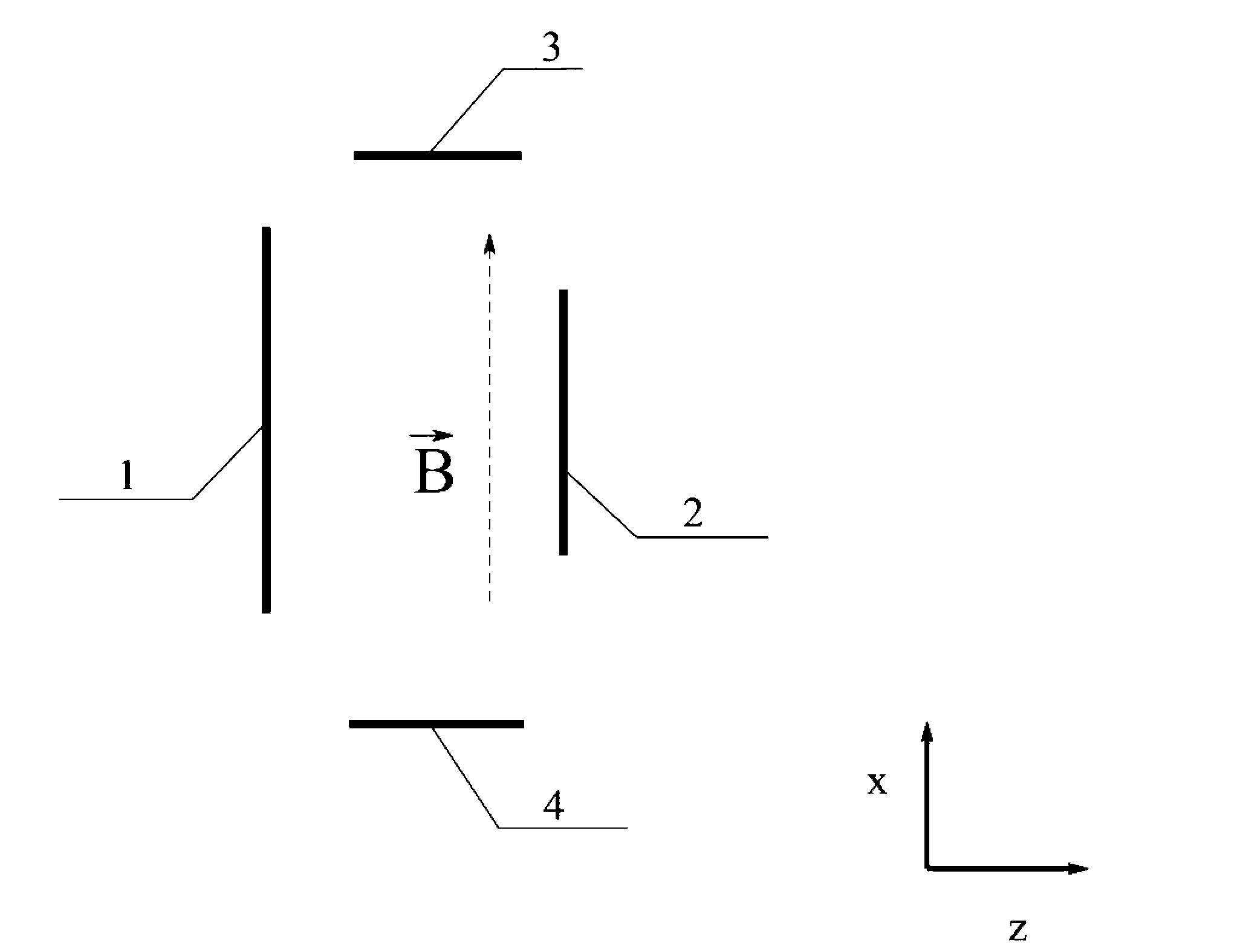
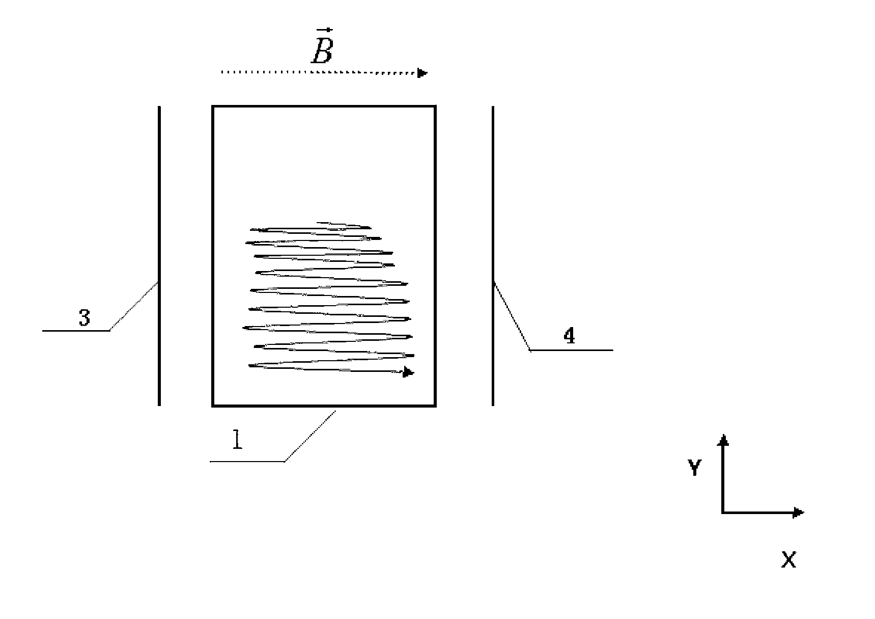
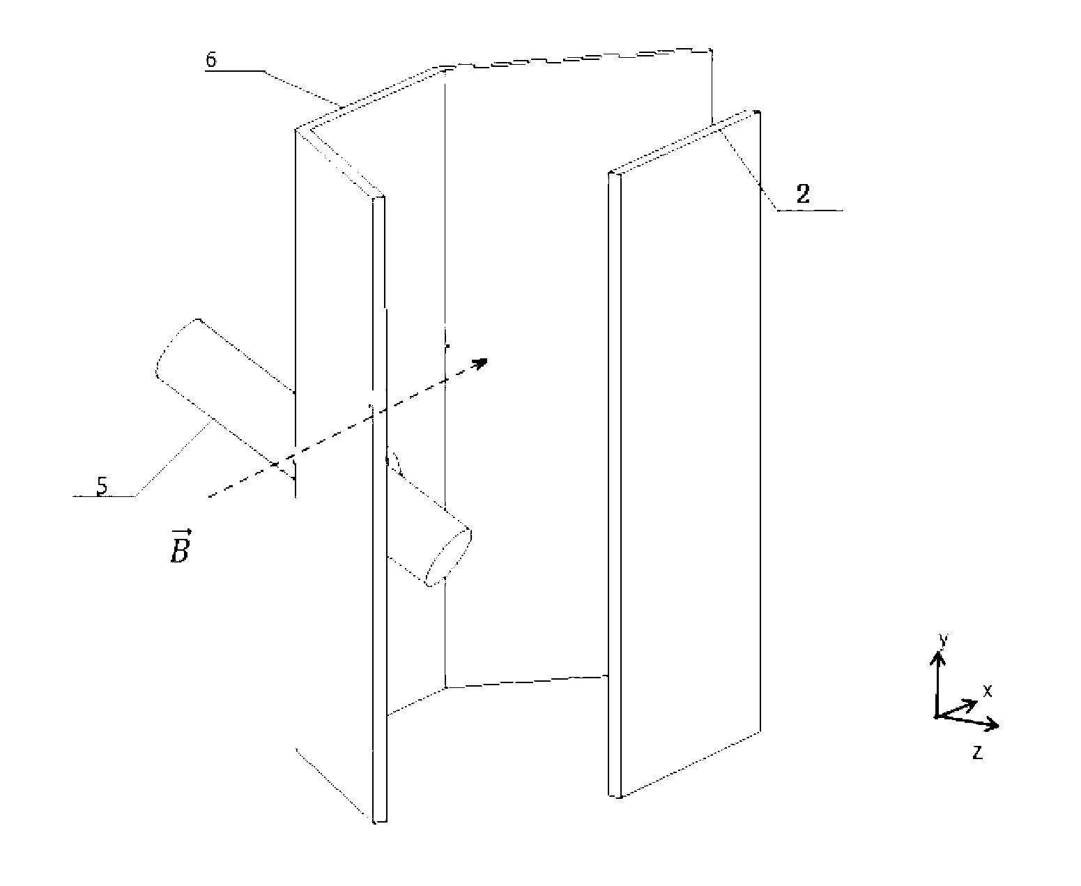
[0020] The method of the present invention constructs a new electric field configuration in the direction orthogonal to the magnetic field, the component of the electric field perpendicular to the magnetic field direction is much larger (generally referring to more than 10 times) the component parallel to the magnetic field direction, and perpendicular to the magnetic field direction The electric field component is called the drift electric field, and the electric field component parallel to the direction of the magnetic field is called the potential well. Under the constraint of the potential well,...


PUM


Abstract

The invention discloses an electro beam ejection restraint method and device under a strong magnetic field. The method comprises the following steps: an electric field is additionally arranged in a magnetic field and forms a potential trap configuration along the direction of the magnetic field, a drifting field is formed in a direction vertical to the magnetic field, and in the potential trap, an electro beam does reciprocating movement along the direction of a magnetic line under the action of electric field force component, and traverses the magnetic line at drifting speed of the electric field in direction vertical to the magnetic line. The device comprises a cathode plate, an anode plate, a cathode, and a first and second trap pole plate. In the method, through restraint of the potential trap, the electron beam is restrained effectively in a direction parallel to the magnetic field and traverses the magnetic field at the drifting speed of the electric field. For the device, after the cathode generates the electro beam, the electron beam is well restrained in a direction parallel to the magnetic field and traverses the magnetic without drift along the magnetic line and influence on the original magnetic field configuration, so that the ejection efficiency is high, and the process is simply and feasibly realized.

Description

technical field [0001] The invention belongs to electron beam injection technology, and in particular relates to a method and device for confining an electron beam across a magnetic field under a strong magnetic field. The invention is especially suitable for the field of controlled nuclear fusion engineering. Background technique [0002] In high-energy physics and controllable fusion research, in many cases it is necessary to move the electron beam across the magnetic field lines, and in the presence of a strong magnetic field (generally refers to a magnetic field above 1T), the electron beam is not restricted along the direction of the magnetic field Most of the force will drift away directly along the magnetic force line, and it is difficult to inject across the magnetic force line. [0003] The traditional methods for solving this problem include the following. U.S. patent document Patent Number: 5,225,146; Date of Patent: On July 6, 1993, a principle of magnetic field ...

Claims


Application Information

Patent Timeline
IPC IPC(8): G21B1/05
CPCY02E30/126Y02E30/10
Inventor 丁永华金海王能超岑义顺
Owner HUAZHONG UNIV OF SCI & TECH
Why Eureka
Try Eureka