Solar field power supply system

A technology of power supply system and solar energy, which is applied in the direction of current collectors, electric vehicles, electrical components, etc., can solve the problems of load inoperability, inability to provide power to load, damage, etc., to prolong the time and times of charging and discharging, realize automatic management, The effect of extending the service life

Inactive Publication Date: 2012-10-03
上海桥茵自动化设备有限公司
View PDF4 Cites 1 Cited by
  • Summary
  • Abstract
  • Description
  • Claims
  • Application Information

AI Technical Summary

Problems solved by technology

Normally, when the battery is being charged, the voltage between the two poles will be higher than the normal working voltage of the battery, so the working voltage of the load will also be higher than its normal working voltage, as a result, some loads will not work or be damaged
In addition, once the battery is damaged due to failure, the charge controller may not work normally, which will make the load unable to work.
[0004] Because the charge controllers currently on the market use battery voltage stabilization technology, when the battery is in an under-power state and the voltage is lower than the minimum operating voltage of the load, the charge controller will charge the battery and must wait until the battery voltage rises to the load power supply. When the voltage value is turned on, the load can receive power supply. Due to the instability of solar power generation and the uncertainty of the recovery speed of the battery in the state of low power, this period of time will be unpredictable, and it may eventually make solar power generation The system is useless and cannot provide power to the load
[0005] In addition, the charging capacity of the charging controllers sold in the market refers to the normal charging current value of the charging controller. Regardless of the actual capacity of the battery being charged, the output current of the charging controller is the maximum current, which is constant (capable The maximum output current is constant), so a large part of this type of charge controller cannot meet the needs of different capacity batteries for charging current control

Method used


Image

  • Solar field power supply system
  • Solar field power supply system
  • Solar field power supply system

Examples


Embodiment Construction

[0028] In order to make the technical means, creative features, goals and effects achieved by the present invention easy to understand, the present invention will be further described below in conjunction with specific illustrations.

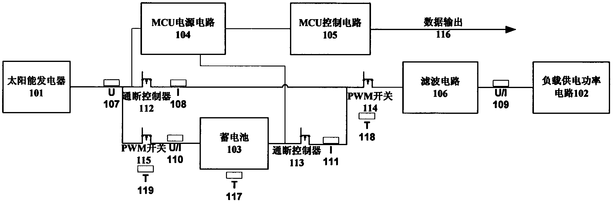
[0029] like figure 1 As shown, as the first solution of the system of the present invention, this solar on-site power supply system includes a solar photovoltaic device 101 , a filter circuit 106 , a load supply power circuit 102 , a storage battery 103 , an MCU power supply circuit 104 and an MCU control circuit 105 . Wherein, an on-off controller 112 and a PWM switch 114 are further provided between the solar photovoltaic device 101 and the filter circuit 106 . A PWM switch 115 is also provided between the solar photovoltaic device 101 and the storage battery 103 . An on-off controller 113 is also provided between the battery 103 and the PWM switch 114 .

[0030] The whole system is powered by solar photovoltaic devices to supply power to tw...


PUM


Abstract

The invention discloses a solar field power supply system which comprises a solar photovoltaic device, a filter circuit, a load power supply circuit, a storage battery, a microprogrammed control unit (MCU) power circuit and an MCU control circuit, wherein the solar photovoltaic device is in circuit connection with the storage battery to achieve charging of the storage battery, and a pulse-width modulation (PWM) switch used for adjusting charging energy supply is arranged between the solar photovoltaic device and the storage battery. The solar photovoltaic device is in circuit connection with the filter circuit to achieve direct power supply for a load, and a PWM switch used for adjusting energy supply is arranged between the solar photovoltaic device and the filter circuit. The storage battery is in circuit connection with the filter circuit so that the storage battery can supply power to the load, and an on-off controller for on-off controlling is arranged between the storage battery and the filter circuit. The filter circuit is circuit connection with the load power supply circuit to supply stable electric power to the load power supply circuit. The MCU power circuit obtains electricity by respectively being connected with the solar photovoltaic device and the storage battery and simultaneously supplies power to the MCU control circuit which is connected with the MCU power circuit.

Description

Technical field: [0001] The invention relates to a power supply system, in particular to a solar field power supply system. Background technique: [0002] With the continuous popularization of solar power generation in off-grid systems, solar charge controllers have been used on a large scale. People hope that solar power generation can be used very stably in related remote places that are not convenient for power construction. [0003] However, almost all the solar charge controllers currently on the market use battery voltage stabilization technology, which is to use the storage capacity of the battery to stabilize the charging and load work, so when the voltage at the two poles of the battery is relatively low, the battery can play a part of the regulator. Normally, when the battery is being charged, the voltage between the two poles will be higher than the normal working voltage of the battery, so the working voltage of the load will also be higher than its normal worki...

Claims


Application Information

Patent Timeline
Patent Type & Authority Applications(China)
IPC IPC(8): H02J7/00
Inventor 吴勇彪
Owner 上海桥茵自动化设备有限公司
Why Eureka
Try Eureka