Machine to machine (M2M) communication method and processing equipment

A technology for processing equipment and communication methods, applied in the field of Internet of Things

Active Publication Date: 2012-10-03
HUAWEI TECH CO LTD
View PDF3 Cites 4 Cited by
  • Summary
  • Abstract
  • Description
  • Claims
  • Application Information

AI Technical Summary

Problems solved by technology

Existing solutions do no

Method used


Image

  • Machine to machine (M2M) communication method and processing equipment
  • Machine to machine (M2M) communication method and processing equipment
  • Machine to machine (M2M) communication method and processing equipment

Examples


Embodiment approach 1

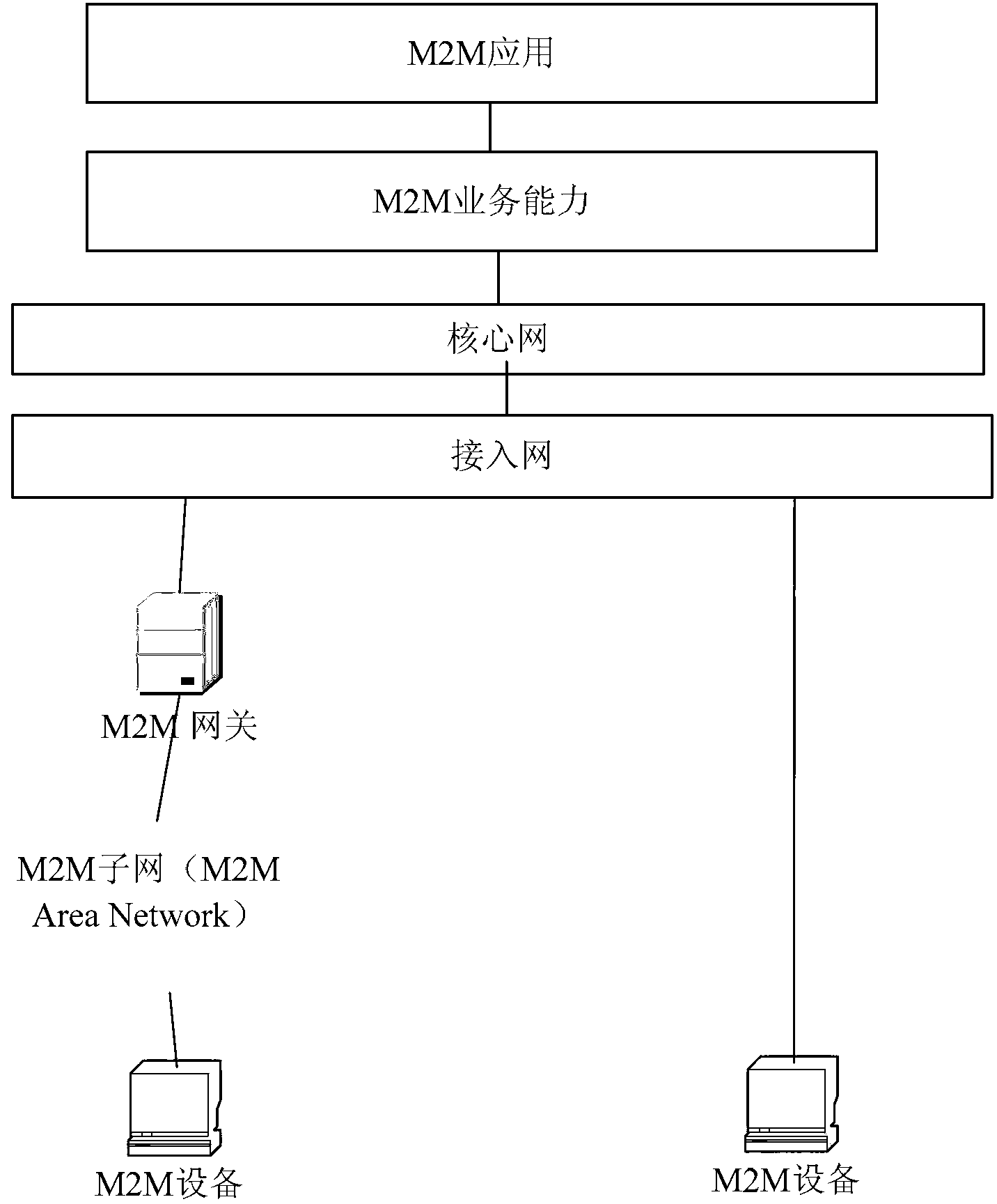
[0018] In M2M communication scenarios, such as Figure 1A As shown, it is a possible application environment of the application of the present invention, and the application system includes the following elements or devices:

[0019] An M2M device is a device that can run one or more M2M services by using one or more M2M capabilities. There are two ways for M2M devices to access the network: one is direct access, "Direct Connectivity", where M2M devices are connected to the network side through the access network; the other is through M2M gateway access, "Gateway as a Network Proxy", the M2M device is connected to the network side through one or more M2M gateways. The M2M device is connected to the M2M gateway through an M2M local area network (M2M Area Network). The basic functions of the above devices can refer to "ETSI TS 102690V1.1.1."

[0020] An M2M local area network (M2M Area Network) is used to provide a network connection between an M2M device and an M2M gateway. ...

Embodiment approach 2

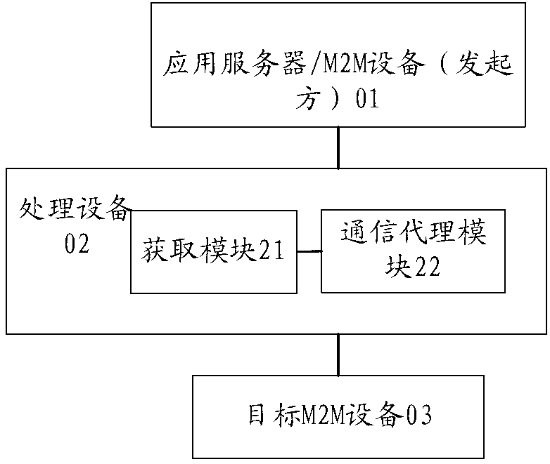
[0061] In the foregoing embodiments of the present invention, refer to figure 2 , there is a special agreement on the interface between the target M2M device and the processing device (02) in the M2M service. The target M2M device needs to explicitly inform the processing device (02) in the M2M service of the time interval ΔT for the next communication establishment, so that The processing device (02) conveniently obtains the establishment time Tm of the next communication. Alternatively, in some existing target M2M devices, the interface described in the aforementioned embodiments of the invention may not be defined, but the historical communication time point information of the M2M device is recorded at the processing device (02), and the next communication establishment is predicted by calculation The time point T'(k+1) of .

[0062] In a specific example, an appropriate statistical prediction algorithm may be adopted correspondingly according to the communication interva...

Embodiment approach 3

[0070] In Embodiment 1 and Method 2 of the present invention, the time point for establishing communication between the target M2M device and the processing device (02) is essentially determined by the target M2M device. In Embodiment 1, the target M2M device decides when to establish communication and sets the time The parameters inform the processing device (02). In example mode 2, the target M2M device still decides when to establish communication, but the processing device (02) needs to calculate and count the time point parameters by itself. For a target M2M device that supports remote communication processing, the processing device (02) can also dynamically adjust and process the communication time interval according to the needs of the business scenario, and notify the target M2M device through a remote command.

[0071] The above methods can include:

[0072] 501-502. The processing device (02) collects the communication interval adjustment instruction of the initiato...


PUM


Abstract

The invention provides processing equipment (02) applied to a machine to machine (M2M) service. The processing equipment (02) communicates with an initiator (01) and target M2M equipment (03), receives a service message sent by the initiator to the target M2M equipment and comprises an acquisition module (21) for acquiring a working state of the target M2M equipment, a time point Tm of next time of communication of the target M2M equipment, overdue time Ta of the service message and an instruction on whether to awake the target M2M equipment forcibly, and a communication agent module (22) for processing the service message according to the working state of the target M2M equipment, the time point Tm of the next time of communication, the overdue time Ta of the service message and the instruction on whether to awake the target M2M equipment forcibly.

Description

technical field [0001] The present invention relates to the Internet of Things technology, in particular to a processing device or an M2M information communication method. Background technique [0002] The M2M technology refers to a machine-to-machine (Machine to Machine) communication technology. In the application scenario of the Internet of Things, due to various reasons, the use of communication resources by M2M devices is limited, so that communication is often in an unreachable state. For example: based on the consideration of power saving, M2M devices will be in the sleep state as much as possible; or, the massive number of M2M devices exacerbates the scarcity of operator network communication resources (such as: IP addresses, communication channels), and M2M devices need to occupy as little as possible communication resources. On the other hand, different applications have different requirements on the QOS quality (such as reachability and real-time performance) of...

Claims


Application Information

Patent Timeline
IPC IPC(8): H04L12/28H04L12/56H04W52/02
CPCY02D30/70
Inventor 马晓立
Owner HUAWEI TECH CO LTD
Why Eureka
Try Eureka