Rotary atomizing head for electrostatic coating machine
A technology of electrostatic coating and rotary atomization, applied in electrostatic spray device, spray discharge device, spray device, etc., can solve the problem of paint residue and so on
- Summary
- Abstract
- Description
- Claims
- Application Information
AI Technical Summary
Problems solved by technology
Method used
Image

Examples
no. 1 example (
[0069] First embodiment ( Figure 1 to Figure 6 ):
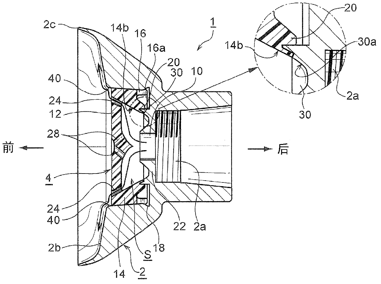
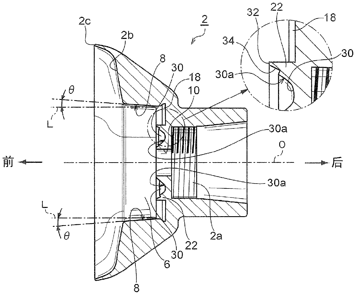
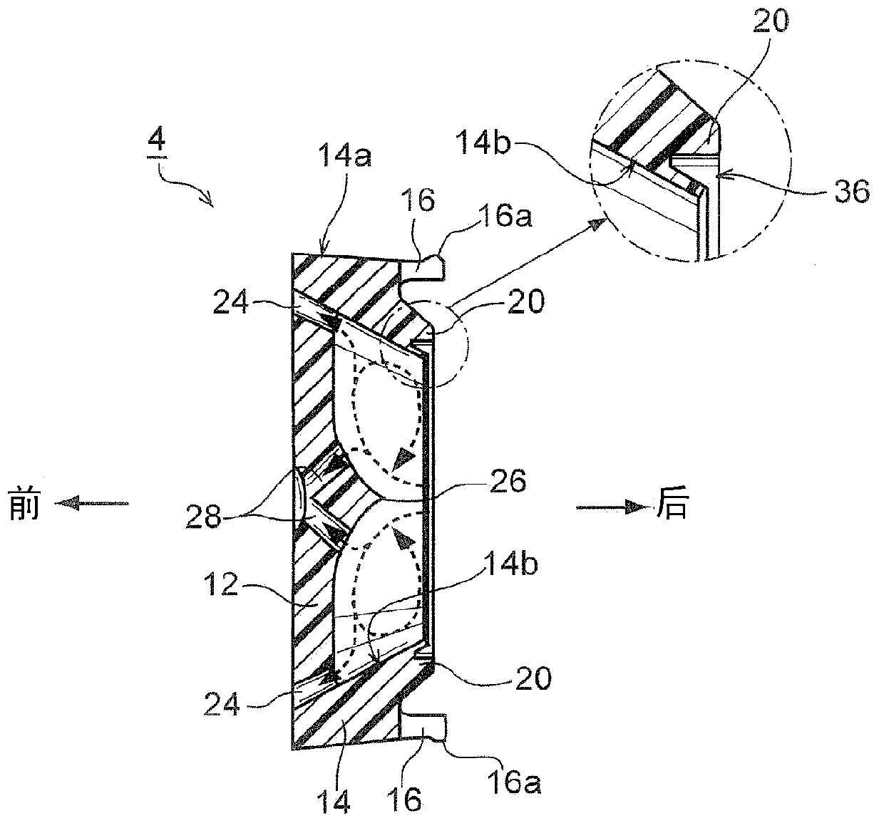
[0070] figure 1 The rotary atomizing head removed from the rotary atomizing type electrostatic coating machine is shown. The illustrated rotary atomizing head 1 is, for example, the same as Patent Document 2 (Japanese Patent Application Laid-Open No. 9-234393 ), which is a combination of an atomizing head main body 2 and a mechanism member 4 arranged at the central portion of the atomizing head main body 2 . Assembled body, the mechanism part 4 can be assembled and disassembled relative to the main body 2 of the atomizing head.
[0071] At the rear end of the atomizing head main body 2, for example, as in Patent Documents 1 and 2, a female screw portion 2a that can be screwed to a shaft (not shown) of an air motor is formed. In addition, the central axis of the female screw portion 2a is the same as the rotation axis of the rotary atomizing head 1, and the rotary atomizing head 1 is driven to rotate by the air motor as in...
no. 2 example (
[0092] The second embodiment ( Figure 7 , Figure 8 ):
[0093] In the first embodiment, the spoon-shaped groove 30 is formed on the atomizing head main body 2, however, in the rotary atomizing head 200 of the second embodiment, the bottom member 202 made of synthetic resin is added, and The aforementioned spoon-shaped groove 30 is formed on the member 202 . That is, in this second embodiment, the paint space S of the rotary atomizing head 200 is formed by two mechanism components 208 , 202 .
[0094] refer to Figure 8 To illustrate in detail, the rotary atomizing head 200 of the second embodiment is composed of an atomizing head main body 204 and a mechanism component 206 assembled thereon, and the mechanism component 206 is composed of a first mechanism component 208 and a separate body from the first mechanism component 208 And the bottom member 202 as an added mechanism component is constituted. The first mechanism part 208 and the bottom member 202 may be molded pr...
no. 3 example (
[0102] The third embodiment ( Figure 9 , Figure 10 ):
[0103] The rotary atomizing head 300 of the third embodiment is also the above-mentioned second embodiment ( Figure 7 , Figure 8 ) modification example. The rotary atomizing head 300 of the third embodiment has no partition wall 216 . In the atomizing head main body 302 of the rotary atomizing head 300 of the third embodiment, the rear end of the large-diameter portion 304 of the housing bottom member 202 is defined by a stepped portion 306 . After the bottom member 202 is installed on the large-diameter portion 304 of the atomizing head main body 302 , the bottom member 202 is locked by the step portion 306 , thereby positioning the bottom member 202 (spoon-shaped groove 202 ).
PUM
 Abstract
Description
Claims
Application Information
 - R&D
- Intellectual Property
- Life Sciences
- Materials
- Tech Scout
- Unparalleled Data Quality
- Higher Quality Content
- 60% Fewer Hallucinations
Browse by: Latest US Patents, China's latest patents, Technical Efficacy Thesaurus, Application Domain, Technology Topic, Popular Technical Reports.
© 2025 PatSnap. All rights reserved.Legal|Privacy policy|Modern Slavery Act Transparency Statement|Sitemap|About US| Contact US: help@patsnap.com