

Exhaust gas purification device of internal combustion engine
An exhaust purification device and exhaust purification technology, which are applied in exhaust devices, internal combustion piston engines, exhaust gas treatment, etc., can solve problems such as the reduction of purification rate, and achieve the effect of high NOX purification rate
- Summary
- Abstract
- Description
- Claims
- Application Information
AI Technical Summary
Problems solved by technology
Method used
Image

Examples
Embodiment Construction
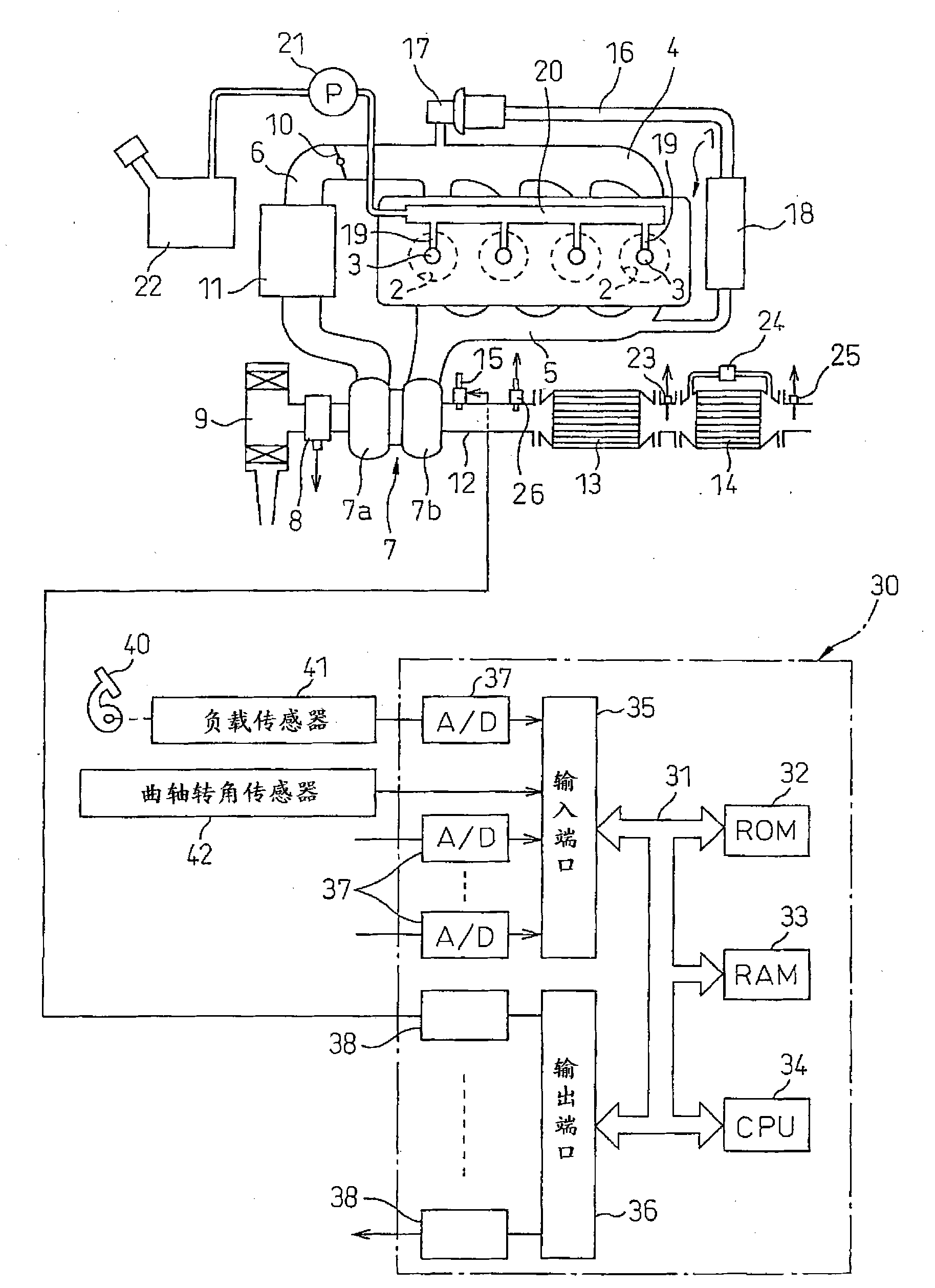
[0039] figure 1 An overall view of a compression ignition internal combustion engine is shown.
[0040] refer to figure 1 , 1 represents the main body of the internal combustion engine, 2 represents the combustion chamber of each cylinder, 3 represents the electronically controlled fuel injection valve for injecting fuel into each combustion chamber 2, 4 represents the intake manifold, and 5 represents the exhaust manifold. The intake manifold 4 is connected to an outlet of a compressor 7 a of an exhaust turbocharger 7 via an intake duct 6 , and an inlet of the compressor 7 a is connected to an air filter 9 via an intake air amount detector 8 . A throttle valve 10 driven by a stepping motor is disposed in the intake duct 6 , and a cooling device 11 for cooling intake air flowing in the intake duct 6 is disposed around the intake duct 6 . exist figure 1 In the exemplary embodiment shown, the engine cooling water is led into the cooling device 11 and the intake air is cooled ...
PUM
 Abstract
Description
Claims
Application Information