
Exhaust emission purifying apparatus for engine

Inactive Publication Date: 2011-10-06
NISSAN DIESEL MOTOR CO
View PDF6 Cites 5 Cited by
  • Summary
  • Abstract
  • Description
  • Claims
  • Application Information

AI Technical Summary

Benefits of technology

[0007]In view of such a problem, the present invention has an object to provide an engine exhaust emission purifying apparatus that can maintain a high NOx purification rate even in the case in which a NOx emission amount from an engine changes suddenly.
[0009]According to the above-mentioned exhaust emission purifying apparatus, before the engine operating state changes due to the change of the transmission speed ratio, the reducing agent or its precursor can be injection-supplied in the amount corresponding to the changed engine operating state (i.e., the engine operating state after the change of the transmission speed ratio). Hence, even in the case in which the NOx emission amount increases due to the change of the engine operating state, a high NOx purification rate in the reduction catalytic converter can be maintained. In addition, in the case in which the NOx emission amount decreases, excessive injection-supply of the reducing agent or its precursor is prevented, so that a high utilization rate of the reducing agent or its precursor can be maintained.

Problems solved by technology

However, since the conventional exhaust emission purifying apparatus mentioned above injection-supplies the urea aqueous solution when an increase in NOx concentration in the exhaust gas is detected, there was a possibility that, for example in the case in which an engine operating state changes suddenly by a driver's shift operation or the like and an NOx amount emitted from the engine increases, a control delay occurs and a sufficient amount of urea aqueous solution may not be injection-supplied, resulting in a decrease in NOx purification rate.

Method used


Image

  • Exhaust emission purifying apparatus for engine
  • Exhaust emission purifying apparatus for engine
  • Exhaust emission purifying apparatus for engine

Examples


Embodiment Construction

[0015]The following describes an embodiment of the present invention with reference to the accompanying drawings.

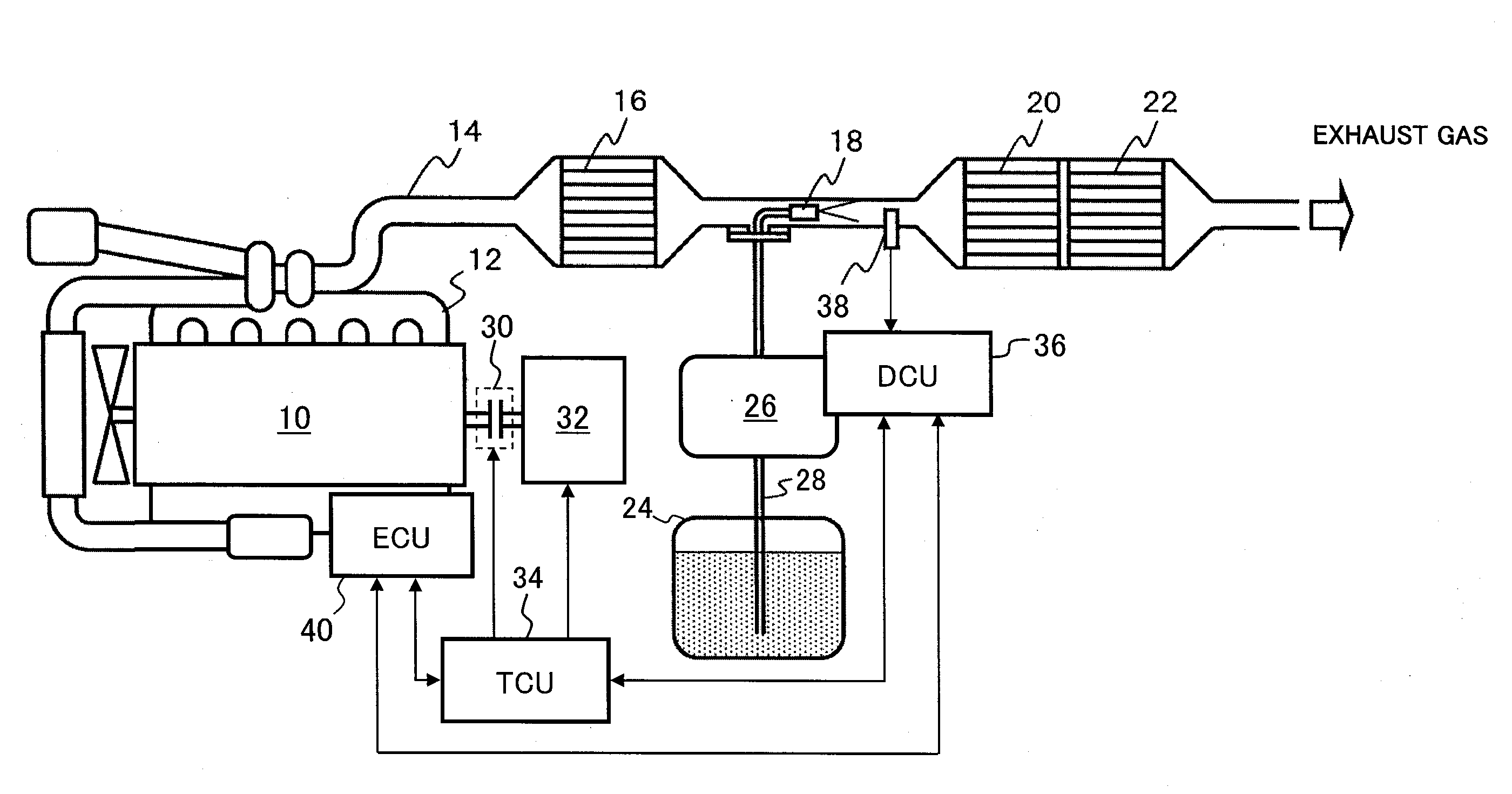
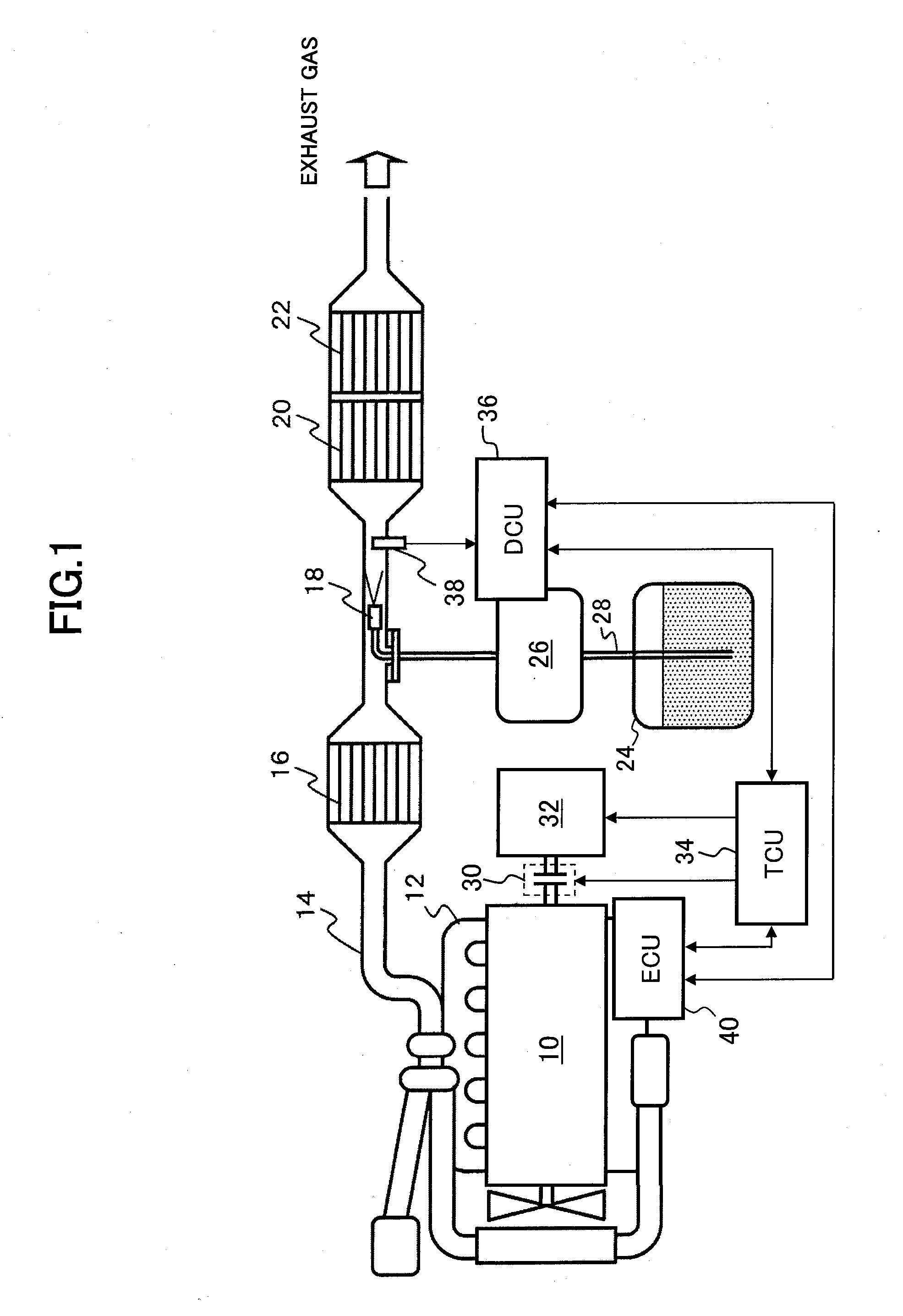
[0016]FIG. 1 illustrates an overall structure of an exhaust emission purifying apparatus for an engine according to an embodiment of the present invention. The exhaust emission purifying apparatus according to this embodiment injection-supplies a urea aqueous solution (a precursor of a reducing agent), to reduce and purify nitrogen oxides (NOx) in exhaust gas by a catalytic reduction reaction using ammonia (the reducing agent) obtained from the urea aqueous solution.

[0017]In FIG. 1, an exhaust pipe 14 is connected to an exhaust manifold 12 of an engine 10. In this exhaust pipe 14, a nitrogen oxidation catalytic converter 16 that oxidizes nitric oxide (NO) in the exhaust gas to convert it to nitrogen dioxide (NO2), an injection nozzle 18 that injection-supplies the urea aqueous solution into the exhaust pipe 14, an NOx reduction catalytic converter 20 that reduces and puri...


PUM


Abstract

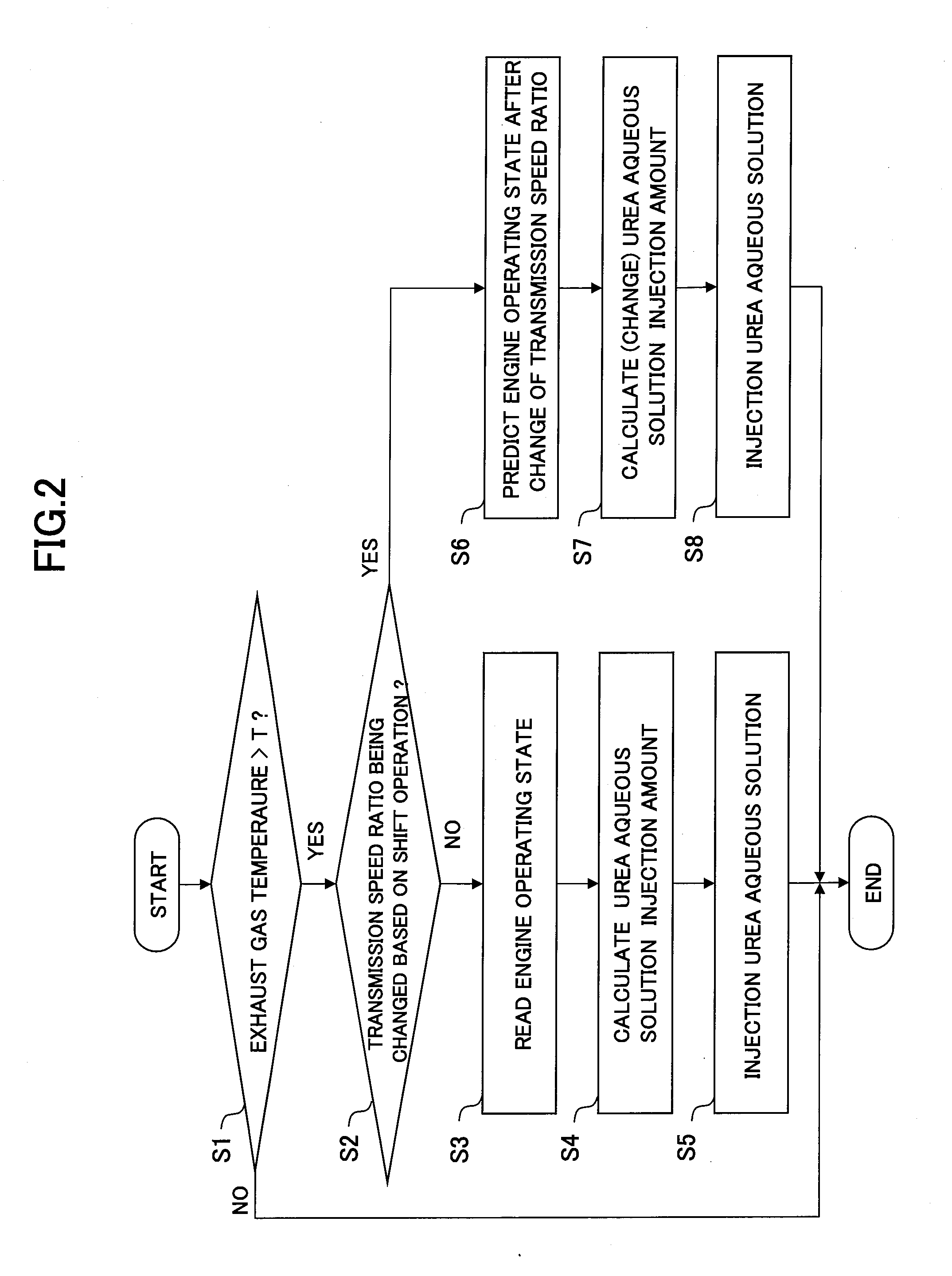
In order to maintain a high NOx purification rate of a NOx reduction catalytic converter even in the case in which an NOx emission amount from an engine changes suddenly, in an exhaust emission purifying apparatus for an engine that reduces and purifies NOx in exhaust gas using ammonia generated from an injection-supplied urea aqueous solution, after engine starting, when an exhaust temperature exceeds a predetermined temperature T (step S1), an amount of urea aqueous solution corresponding to an actual engine operating state is injection-supplied (steps S3 to S5). On the other hand, at a change of the transmission speed ratio based on a driver's shift operation, an engine operating state after the change of the transmission speed ratio is predicted (steps S2, S6), and an amount of urea aqueous solution corresponding to the predicted engine operating state is injection-supplied before the change of the transmission speed ratio is completed (steps S7, S8).

Description

[0001]This application is a continuation of PCT / JP2009 / 067255, filed on Oct. 2, 2009.BACKGROUND OF THE INVENTION[0002]1. Field of the Invention[0003]The present invention relates to an exhaust emission purifying apparatus for an engine that reduces and purifies nitrogen oxides (NOx) in exhaust gas using a reducing agent.[0004]2. Description of Related Art[0005]As an exhaust emission purifying apparatus that purifies NOx contained in exhaust gas from an engine, an exhaust emission purifying apparatus using ammonia as a reducing agent was known. For example, an exhaust emission purifying apparatus disclosed in Japanese Patent Application Publication No. 2000-27627 injection-supplies a urea aqueous solution to an upstream side of a NOx reduction catalytic converter positioned in an exhaust passage, to reduce and purify NOx in exhaust gas by ammonia that is generated from the urea aqueous solution.[0006]However, since the conventional exhaust emission purifying apparatus mentioned above...

Claims


Application Information

Patent Timeline
IPC IPC(8): F01N3/10F01N3/18
CPCF01N3/105F01N3/208F01N2560/06Y10T477/663F01N2900/08Y02T10/24F01N13/009F01N2610/02Y02T10/12
Inventor YANO, MASAKAZUHIRATA, KIMINOBUMASAKI, NOBUHIKO
Owner NISSAN DIESEL MOTOR CO
Learn More