Exhaust gas clarifying device for internal combustion engine
- Summary
- Abstract
- Description
- Claims
- Application Information
AI Technical Summary
Benefits of technology
Problems solved by technology
Method used
Image
Examples
Embodiment Construction
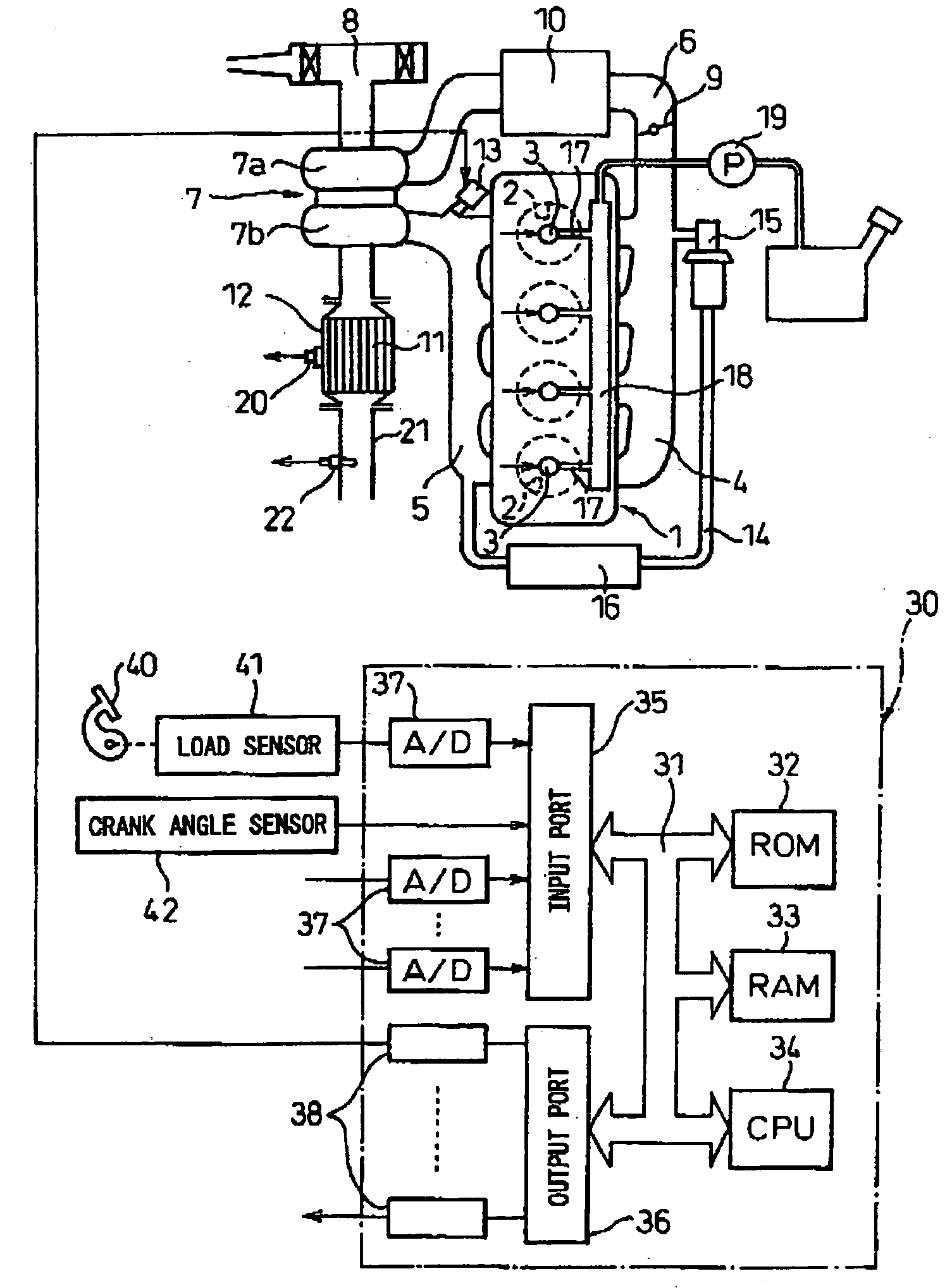
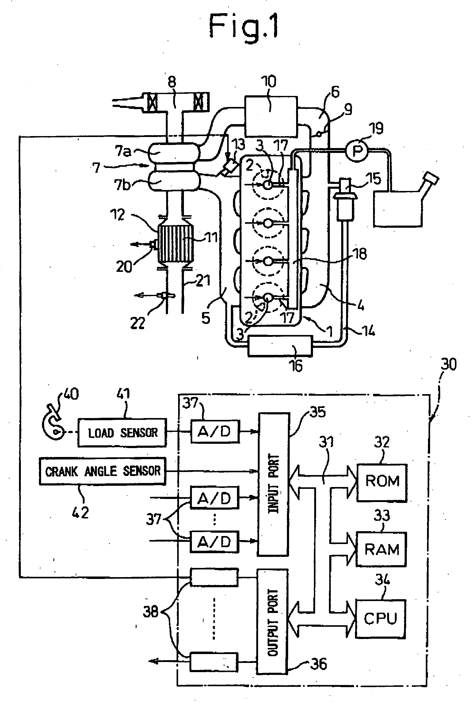
[0059]FIG. 1 shows the case of application of the present invention to a compression ignition type internal combustion engine. Note that the present invention may also be applied to a spark ignition type internal combustion engine.
[0060] Referring to FIG. 1, 1 indicates an engine body, 2 a combustion chamber of each cylinder, 3 an electronically controlled fuel injector for injecting fuel into each combustion chamber 2, 4 an intake manifold, and 5 an exhaust manifold. The intake manifold 4 is connected through an intake duct 6 to an outlet of a compressor 7a of an exhaust turbocharger 7. The inlet of the compressor 7a is connected to an air cleaner 8. Inside the intake duct 6 is arranged a throttle valve 9 driven by a step motor. Further, around the intake duct 6 is arranged a cooling device 10 for cooling the intake air flowing through the inside of the intake duct 6. In the embodiment shown in FIG. 1, the engine cooling water is guided into the cooling device 10. The engine cooli...
PUM
| Property | Measurement | Unit |
|---|---|---|
| Temperature | aaaaa | aaaaa |
| Temperature | aaaaa | aaaaa |
| Temperature | aaaaa | aaaaa |
Abstract
Description
Claims
Application Information
 - R&D
- Intellectual Property
- Life Sciences
- Materials
- Tech Scout
- Unparalleled Data Quality
- Higher Quality Content
- 60% Fewer Hallucinations
Browse by: Latest US Patents, China's latest patents, Technical Efficacy Thesaurus, Application Domain, Technology Topic, Popular Technical Reports.
© 2025 PatSnap. All rights reserved.Legal|Privacy policy|Modern Slavery Act Transparency Statement|Sitemap|About US| Contact US: help@patsnap.com


