
Exhaust purification system for internal combustion engine

a technology for exhaust purification and internal combustion engines, which is applied in the direction of machines/engines, electrical control, separation processes, etc., can solve the problems of inability to map parameters in all operating regions, inability to maintain the nosub>2/sub>—nox ratio at 0.5 under such conditions, and inability to avoid deterioration of fuel economy and marketability. achieve the effect of increasing the nox purification rate to be high

Active Publication Date: 2012-10-11
HONDA MOTOR CO LTD
View PDF3 Cites 32 Cited by
  • Summary
  • Abstract
  • Description
  • Claims
  • Application Information

AI Technical Summary

Benefits of technology

[0010]As described above, control to continuously maintain the NO2—NOx ratio at the optimum value such as that of the technology illustrated in Patent Document 1 is not only difficult in actual practice, but also cannot avoid deterioration in the fuel economy and marketability even if it were possible.
[0036]The HC that is the NO2 reduction component as described above reduces NO2 in the NOx selective reduction catalyst to make NO; which means that there being a function of adsorbing HC in the NOx selective reduction catalyst is considered almost synonymous with improving the NO2 adsorption function of the NOx selective reduction catalyst. Therefore, in NO2—NOx ratio perturbation control, the region in which the NO2—NOx ratio can be made to change can be widened; therefore, the NOx purification rate can be more steadily maintained to be high.

Problems solved by technology

However, although the operating state of an internal combustion engine is always changing depending on the demands of the operator, the state of the vehicle, etc., continuously maintaining the NO2—NOx ratio at 0.5 under such conditions is very difficult in actual practice.
; however, these parameters cannot be mapped in all operating regions so that the NO2—NOx ratio is 0.5.
In addition, even if it were assumed that such mapping were possible, in this case, deterioration of the fuel economy and marketability could not be avoided.
As described above, control to continuously maintain the NO2—NOx ratio at the optimum value such as that of the technology illustrated in Patent Document 1 is not only difficult in actual practice, but also cannot avoid deterioration in the fuel economy and marketability even if it were possible.

Method used


Image

  • Exhaust purification system for internal combustion engine
  • Exhaust purification system for internal combustion engine
  • Exhaust purification system for internal combustion engine

Examples


first embodiment

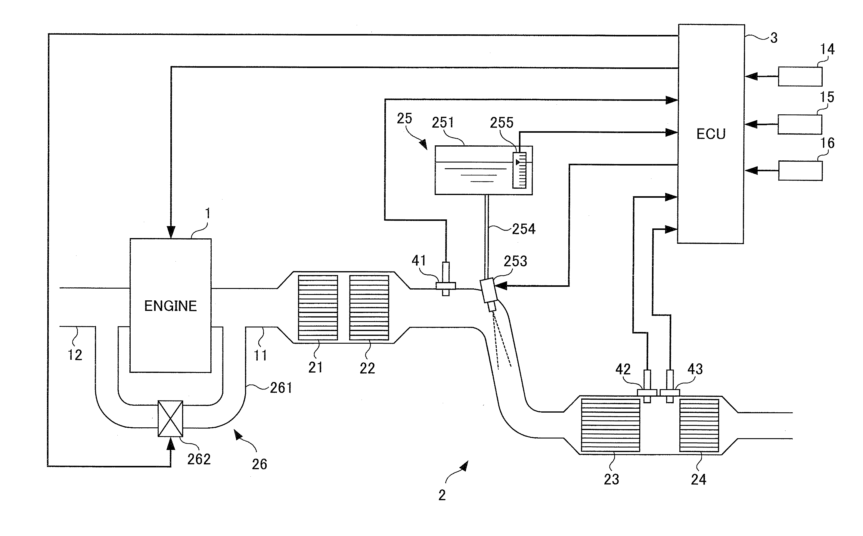
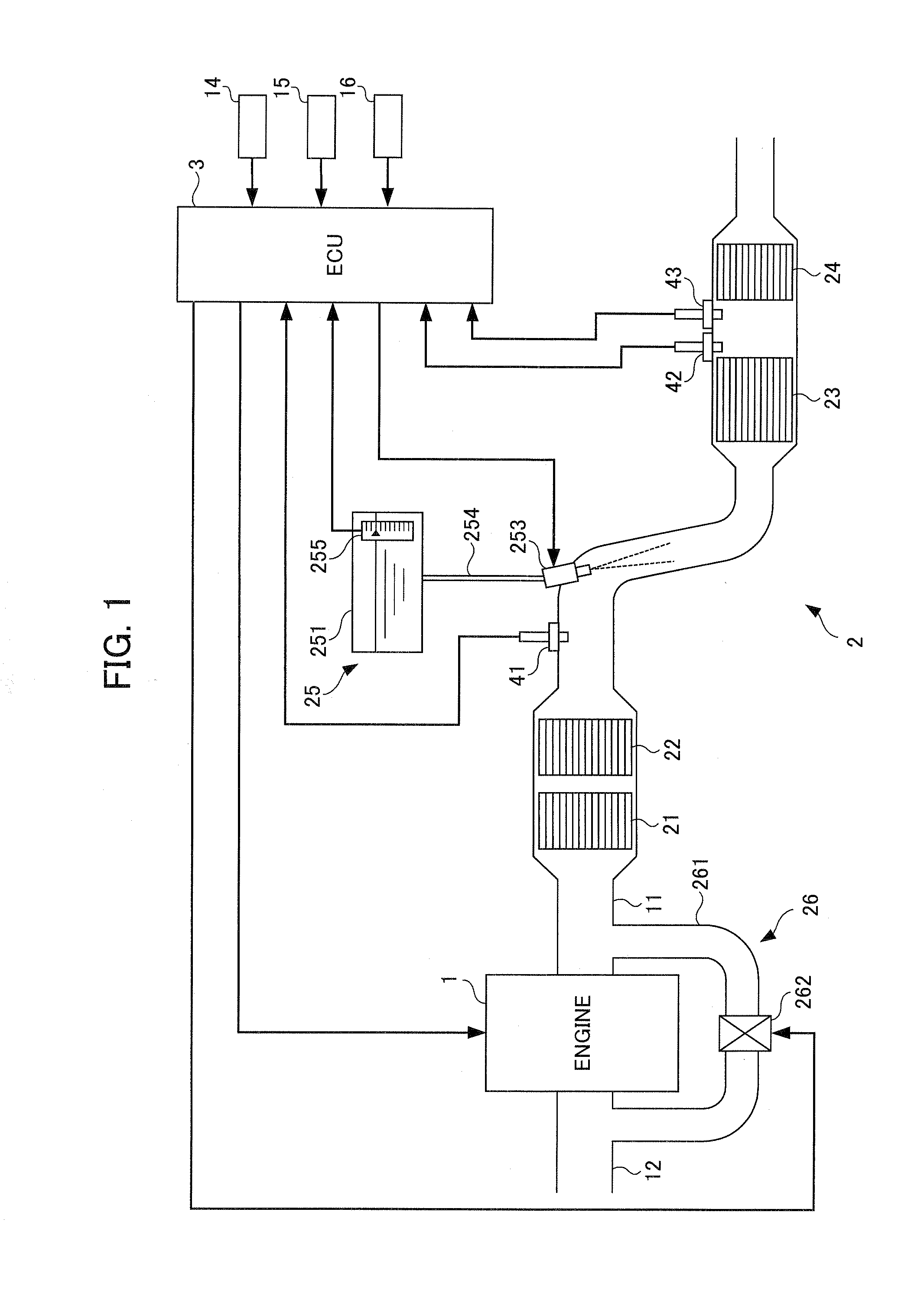
[0058]Hereinafter, a first embodiment of the present invention will be explained while referring to the drawings. FIG. 1 is a schematic diagram showing the configuration of an internal combustion engine (hereinafter referred to as “engine”) 1 and an exhaust purification system 2 thereof according to the present embodiment. The engine 1 is a gasoline engine of lean-burn operating type or a diesel engine, and is mounted in a vehicle, which is not illustrated.

[0059]The exhaust purification system 2 is configured to include an oxidation catalyst 21 provided in exhaust plumbing 11 of the engine 1, a CSF (Catalyzed Soot Filter) 22 that is provided in the exhaust plumbing 11 and collects soot in the exhaust, a selective reduction catalyst 23 that is provided in an exhaust plumbing 11 and purifies NOx in the exhaust flowing through this exhaust plumbing 11 under the presence of NH3 serving as a reducing agent, a urea injection device 25 that supplies urea water, which is a precursor of ammo...

second embodiment

[0199]Next, a second embodiment of the present invention will be explained while referring to the drawings. It should be noted that, in the following explanation, the same symbols are assigned for similar configurations to the first embodiment, and explanations thereof will be omitted.

[0200]In the selective reduction catalyst containing zeolite as described above, a function of adsorbing HC is also possessed in addition to the function of adsorbing NO2. In addition, the HC adsorbed to the selective reduction catalyst reduces NO2, which is the main factor making the NOx purification rate and NO2 storage amount of the selective reduction catalyst vary. The present embodiment differs from the above-mentioned first embodiment in the aspect of accounting for such adsorption of HC on the selective reduction catalyst.

[0201]FIG. 20 is a block diagram showing the configuration of a catalyst parameter estimation device 5A.

[0202]In the present embodiment, the configuration of a selective reduc...


PUM

PropertyMeasurementUnit
mole ratioaaaaaaaaaa
temperatureaaaaaaaaaa
adsorptionaaaaaaaaaa

Abstract

An exhaust purification system for an internal combustion engine is provided that can steadily maintain a NOx purification rate of a selective reduction catalyst to be high without allowing the fuel economy or marketability to deteriorate. The exhaust purification system includes a NO2—NOx ratio adjustment mechanism that causes a NO2—NOx ratio to change; and a NO2—NOx ratio perturbation controller that executes NO2—NOx ratio perturbation control so that a NO2 balance of the selective reduction catalyst in a predetermined time period, with NO2 adsorption being positive and NO2 release being negative, is 0. Herein, NO2—NOx ratio perturbation control is defined as control that alternately executes NO2 increase control to cause the NO2—NOx ratio to be greater than a reference value near 0.5, and NO2 decrease control to cause the NO2—NOx ratio to be less than the reference value.

Description

[0001]This application is based on and claims the benefit of priority from Japanese Patent Application No. 2011-083960, filed on 5 Apr. 2011, the content of which is incorporated herein by reference.BACKGROUND OF THE INVENTION[0002]1. Field of the Invention[0003]The present invention relates to an exhaust purification system for an internal combustion engine. More specifically, it relates to an exhaust purification system for an internal combustion engine equipped with a selective reduction catalyst that selectively reduces nitrogen oxides (NOx) in the exhaust under the presence of a reducing agent.[0004]2. Related Art[0005]As one exhaust purification system that purifies NOx in exhaust, a system has thus far been proposed in which a selective reduction catalyst that selectively reduces NOx in the exhaust by way of a reducing agent such as ammonia (NH3) is provided in an exhaust channel. For example, with an exhaust purification system of urea addition type, urea water, which is a N...

Claims


Application Information

Patent Timeline
Patent Type & Authority Applications(United States)
IPC IPC(8): F01N3/10
CPCF02D41/0055F01N13/0097F02D41/10F02D41/1446F02D41/146F02D2041/1468F02D2200/0802F02D2200/0806Y02T10/47B01D53/9418B01D53/944B01D53/9477B01D2255/50B01D2255/91B01D2255/912F01N3/0814F01N3/106F01N3/2066F01N3/208F01N2370/04F01N2560/026F01N2570/14Y02T10/24F01N13/009F02D41/0275Y02A50/20Y02T10/12Y02T10/40
Inventor MATSUNAGA, HIDEKIYASUI, YUJIHASHIMOTO, EIJIHAGA, HISAOSATO, NAOHIROSAKOTA, MASAFUMI
Owner HONDA MOTOR CO LTD
Learn More