Heat transfer tube for heat exchanger, heat exchanger, refrigeration cycle device, and air conditioning device
A technology for heat exchangers and circulation devices, applied in the field of heat transfer tubes, can solve the problems of reduced close contact between heat transfer tubes and fins, reduced heat transfer performance, increased pressure loss, etc. The effect of elastic and improved close contact
- Summary
- Abstract
- Description
- Claims
- Application Information
AI Technical Summary
Problems solved by technology
Method used
Image

Examples
Embodiment approach 1
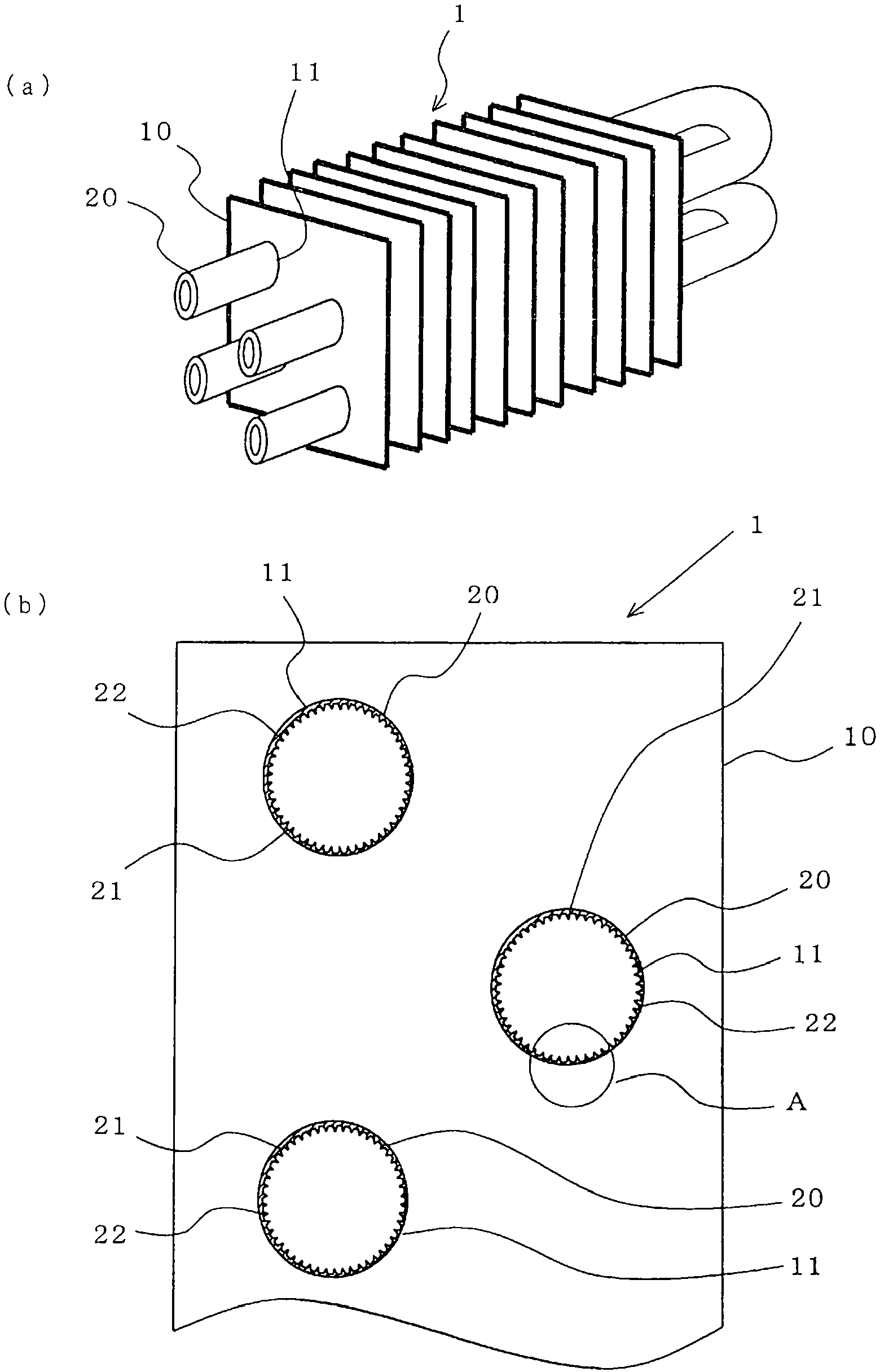
[0029] exist figure 1 Among them, the heat exchanger 1 is a finned tube type heat exchanger widely used as an evaporator or a condenser of a refrigeration device, an air conditioner, or the like.
[0030] The heat exchanger 1 is composed of a plurality of heat exchanger fins 10 and heat transfer tubes 20 . A through-hole 11 is provided in each of the plurality of fins 10 arranged in parallel at predetermined intervals, and the heat transfer tube 20 penetrates through the through-hole 11 . The heat transfer tube 20 becomes a part of the refrigerant circuit in the refrigerating cycle apparatus, and the heat of the refrigerant flowing inside the heat transfer tube 20 and the air flowing outside is transferred through the fins 10, thereby expanding the heat transfer area, and the refrigerant and the Air heat exchange is performed efficiently.
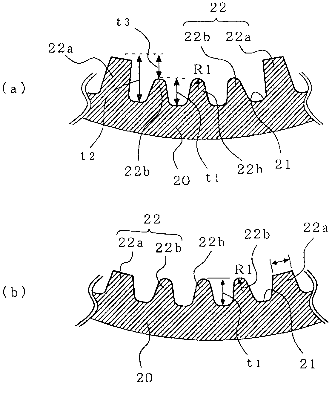
[0031] Such as figure 2 As shown, the tube inner surface of the heat transfer tube 20 is provided with grooves 21 and peaks 22 through...
Embodiment approach 2
[0042] Figure 6 The shape of the tube inner surface of the heat transfer tube 20 according to the second embodiment of the present invention is shown, and the structure of the heat exchanger 1 is the same as that of the first embodiment. In addition, the same code|symbol is attached|subjected to the part which plays the same or equivalent function as Embodiment 1 (it is also the same in the following embodiment). In this embodiment, the difference H between the groove portion 21 and the peak portion 22 after pipe expansion will be described.
[0043] Figure 7 The relationship between the difference between the groove portion 21 and the peak portion 22 after tube expansion (the peak portion 22a after tube expansion) and the heat exchange rate is shown. In the heat transfer tube 20, the groove portion 21 and the peak portion after tube expansion The larger the difference H between 22, the larger the surface area inside the tube, etc., and the higher the thermal conductivity....
Embodiment approach 3
[0046] Figure 8 The shape of the tube inner surface of the heat transfer tube 20 according to Embodiment 3 of the present invention is shown, and the straight line parallel to the tube axis direction and the groove part (spiral groove) 21 (peak part 22 ) of the tube inner surface of the heat transfer tube 20 extend. The angle (lead angle or torsion angle) γ formed by the direction is 10 degrees to 50 degrees.
[0047] Figure 9 The relationship between the lead angle γ of the groove portion (spiral groove) 21 of the heat transfer tube 20 and the heat exchange rate is shown. Basically, the lead angle γ of the groove portion (spiral groove) 21 of the heat transfer tube 20 is set at The range of 10° to 50° is because when the lower limit of the lead angle γ of the groove portion (spiral groove) 21 is 10° or less, the decrease in heat exchange rate becomes remarkable, and when the groove portion (spiral groove) When the upper limit of the lead angle γ of 21 is 50 degrees or mor...
PUM
 Abstract
Description
Claims
Application Information
 - R&D
- Intellectual Property
- Life Sciences
- Materials
- Tech Scout
- Unparalleled Data Quality
- Higher Quality Content
- 60% Fewer Hallucinations
Browse by: Latest US Patents, China's latest patents, Technical Efficacy Thesaurus, Application Domain, Technology Topic, Popular Technical Reports.
© 2025 PatSnap. All rights reserved.Legal|Privacy policy|Modern Slavery Act Transparency Statement|Sitemap|About US| Contact US: help@patsnap.com