
Pipe cutting device

A technology for cutting devices and pipes, which is applied in the direction of pipe shearing devices, shearing devices, and accessories of shearing machines, etc. It can solve the problems of cumbersome design, poor forming, and hurting people by splashing debris, and achieve convenience and accuracy. , no material loss, good cutting effect

Inactive Publication Date: 2012-10-10
诸暨市振兴机器制造有限公司
View PDF6 Cites 1 Cited by
  • Summary
  • Abstract
  • Description
  • Claims
  • Application Information

AI Technical Summary

Problems solved by technology

[0004] 1. The above-mentioned types all need to use special cutting tools to cut the material, and the cost of special cutting tools is very high, and the sharpening of special cutting tools in the process of use must use expensive special sharpening equipment for sharpening, use and maintenance high cost;
[0005] 2. Regardless of lathe cutting, sawing machine cutting or circular sawing machine cutting, the lathe cutters, saw blades or circular saw blades used have a certain thickness, resulting in waste of materials during the cutting process;
[0006] 3. Since the pipe to be cut is hollow and cut with a cutting tool of a certain thickness, if the pipe is not very hard, it will easily damage its shape, such as dents, etc., resulting in poor forming;
[0007] 4. The existing cutting method is not safe. For example, cutting the pipe with a lathe, because the pipe must be rotated at high speed, the length of the pipe is greater than the length of the lathe spindle, so the pipe will bring safety problems during the rotation process. Another example is cutting with a knife. It is easy to produce dust and splash and hurt people;
[0008] 5. The existing cutting method is cumbersome in the design of the length fixing and unloading after the pipe is fed in, which increases the production cost and is not easy to operate.

Method used


Image

  • Pipe cutting device
  • Pipe cutting device

Examples


Embodiment Construction

[0024] The implementation of the present invention will be further described in detail below in conjunction with the accompanying drawings.

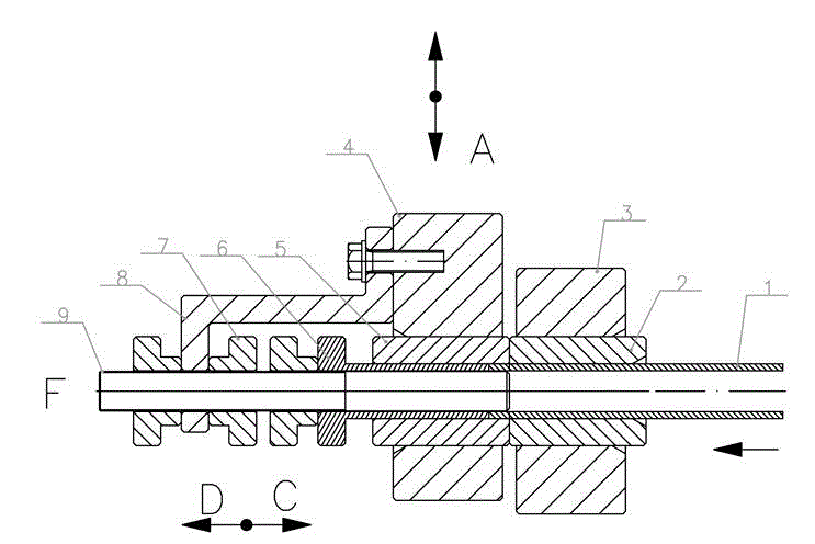
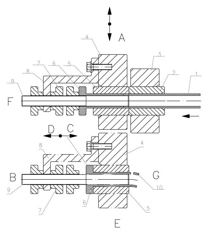
[0025] Such as figure 1 As shown, a pipe cutting device includes a frame. It also includes a fixed knife, a movable knife, a fixed-length support and a power part. The power part is connected with the movable knife, and can push the movable knife to realize punching, cutting off the pipe and reset. The power part itself is an existing technology, such as a motor, etc., as long as it can push the movable knife to realize punching, cutting off the pipe and reset, no further details will be given here.

[0026] The fixed blade includes a fixed blade 2 with an inner hole and a fixed blade seat 3 fixedly connected to the frame, and the movable blade includes a movable blade 5 with an inner hole and a fixed movable blade that is movably connected on the machine. The movable knife edge seat 4 on the frame, the fixed knife edge 2 and the movab...


PUM


Abstract

The invention relates to a pipe cutting device, which comprises a machine frame, a fixed cutter element, a movable cutter element, a fixed length support element and a motive power component, wherein the motive power component is connected with the movable cutter element, the movable cutter element can be pushed to realize the pipe impact load cutting and the resetting, the fixed cuter element comprises a fixed cutting edge and a fixed cutting edge seat, the fixed cutting edge is provided with an inner round hole, the fixed cutting edge seat is used for fixing the fixed cutting edge and is fixedly connected onto the machine frame, the movable cutter element comprises a movable cutting edge and a movable cutting edge seat, the movable cutting edge is provided with an inner round hole, the movable cutting edge seat is used for fixing the movable cutting edge and is movably connected onto the machine frame, the fixed cutting edge and the movable cutting edge are in parallel arrangement and can be matched for realizing the impact load cutting on pipes placed into the two inner round holes, and the fixed length support element comprises a core rod and a top sleeve. The technical scheme of the pipe cutting device provided by the invention has the advantages that the structure is simple, the cost is low, the design is reasonable, the material consumption is low, the purposes are wide, the operation is simple, and the pipe cutting device can be conveniently and safely applicable to the mechanical cutting on round pipes.

Description

technical field [0001] The invention relates to a device for mechanically cutting circular pipes, in particular to a pipe cutting device. Background technique [0002] Cutting machine is an extremely important equipment in the field of pipe body cutting and processing. [0003] Existing known methods of mechanically cutting circular pipes mainly include lathe cutting, sawing machine cutting and circular sawing machine cutting, etc., but there are many defects in use, as follows: [0004] 1. The above-mentioned types all need to use special cutting tools to cut the material, and the cost of special cutting tools is very high, and the sharpening of special cutting tools in the process of use must use expensive special sharpening equipment for sharpening, use and maintenance high cost; [0005] 2. Regardless of lathe cutting, sawing machine cutting or circular sawing machine cutting, the lathe cutters, saw blades or circular saw blades used have a certain thickness, resulting...

Claims


Application Information

Patent Timeline
IPC IPC(8): B23D21/00B23D33/00
Inventor 王德康
Owner 诸暨市振兴机器制造有限公司
Learn More