High-speed reblading mechanism for small drilling and milling center

A tool-changing mechanism, drilling and milling technology, applied in metal processing machinery parts, clamping, support and other directions, can solve the problems of small size of BT15 spindle taper hole, troublesome development needs of precision parts, complex tool-changing mechanism, etc., to reduce labor costs. Labor intensity, high-speed and reliable tool changing mechanism, and the effect of improving production efficiency

Active Publication Date: 2012-10-10
BAOJI XILI PRECISION MACHINERY
View PDF9 Cites 11 Cited by
  • Summary
  • Abstract
  • Description
  • Claims
  • Application Information

AI Technical Summary

Problems solved by technology

In order to process small precision parts such as computer hard disks, the tool diameter is relatively small, so it is necessary to use the BT15 spindle taper hole smaller than the BT30 to achieve high-speed cutting. However, due to the small size and high precision of the BT15 spindle taper hole, the requirements The high tool change speed and complex tool change mechanism have always plagued the development needs of small drilling and milling centers and small precision parts processing in China, so it is necessary to improve

Method used


Image

  • High-speed reblading mechanism for small drilling and milling center
  • High-speed reblading mechanism for small drilling and milling center
  • High-speed reblading mechanism for small drilling and milling center

Examples


Embodiment Construction

[0029] Attached below Figure 1-19 An embodiment of the present invention is described.

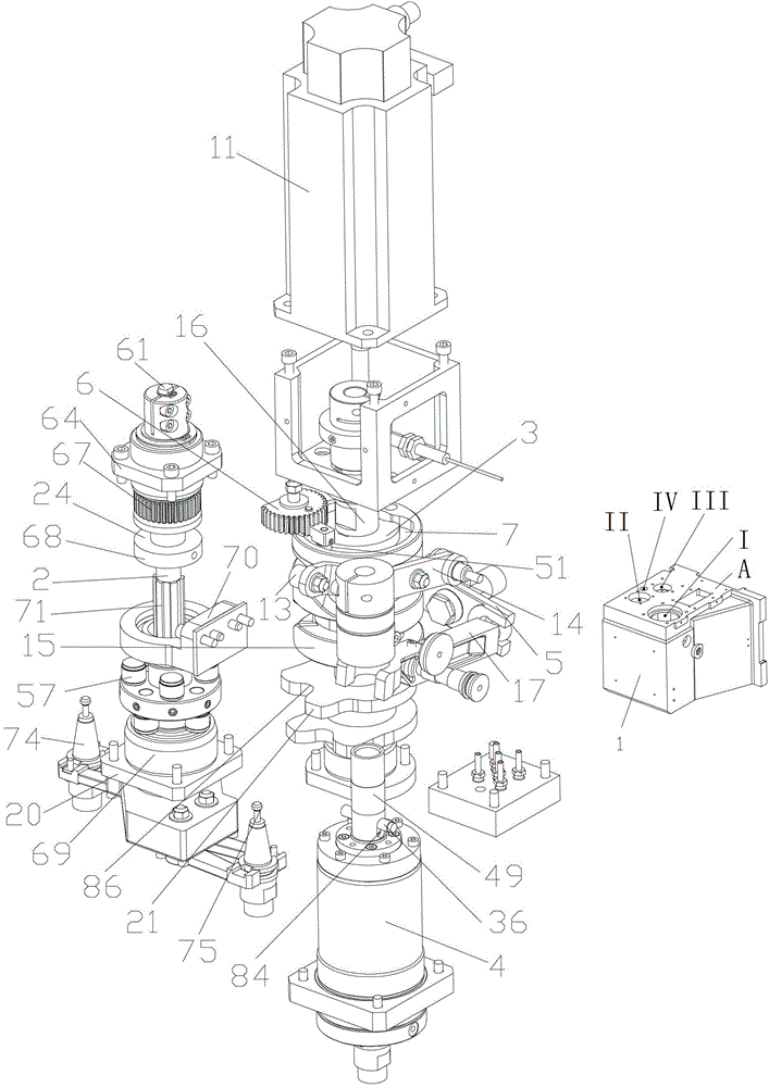
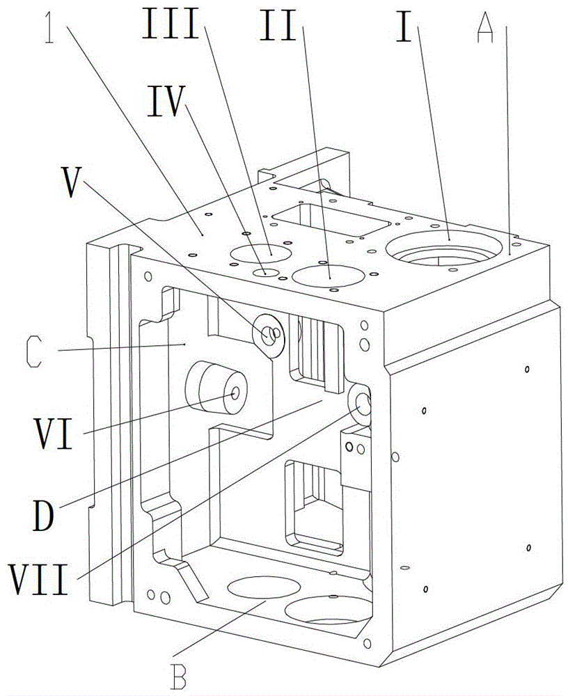
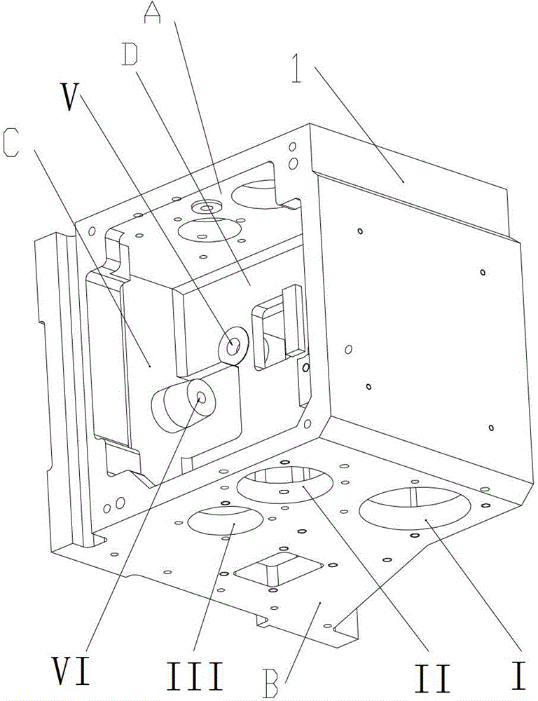
[0030] High-speed tool change mechanism for small drilling and milling centers, with spindle housing 1, such as Figure 2-3 As shown, the A surface of the spindle housing 1 is formed with I, II, III shaft holes penetrating the B surface and the IV axis hole not penetrating the B surface, the C surface is formed with the VI axis hole, and the D surface is formed with the Ⅴ and Ⅶ shaft holes; if figure 1 As shown, the main shaft system 4 is installed in the shaft hole I, and the camshaft system 3 is installed in the shaft hole III. The camshaft 16 of the camshaft system 3 is fitted with an end face cylindrical cam 15 and a plane cam 21 and the end face cylindrical cam 15 is located above the plane cam 21, the end face cylindrical cam 15 is shaped on the end face curved groove 7, the circumference curve groove I8 and the circumference curve groove II12, and the plane cam 21 is shaped on th...


PUM


Abstract

A high-speed reblading mechanism for a small drilling and milling center comprises a spindle box body, a spindle, a cam shaft and a reblading and blade catching mechanism, wherein an end surface cylindrical cam and a planar cam are sleeved on the cam shaft of an axle, a lever mechanism is connected with a limit sleeve on the reblading and blade catching mechanism to achieve downward stretching and upward pulling of the reblading and blade catching mechanism during rotating of the end surface cylindrical cam, ends of the composite lever mechanism are pressed at two ends of a pin shaft on the spindle to achieve clamping or loosening of a blade handle, and the circumferential curved surface on the planar cam is connected with the reblading and blade catching mechanism to achieve 180-degree rotating of the reblading and blade catching mechanism. The end surface cylindrical cam rotates to drive a fan-shaped gear to swing, and the fan-shaped gear is simultaneously meshed with a gear shaft arranged at the upper end of the reblading and blade catching mechanism to achieve opening and closing actions of a blade claw. According to the high-speed reblading mechanism, a cam structure and a hollow spline shaft structure which are arranged in a spindle box are ingeniously used, so that the spindle box is compact in structure. The reblading mechanism is high in speed and reliable so that worker labor intensity is reduced and production efficiency is improved.

Description

technical field [0001] The invention belongs to the technical field of machining centers, and in particular relates to a high-speed tool changing mechanism for small drilling and milling centers. Background technique [0002] In the existing vertical machining center, the taper hole of the main shaft adopts BT30, BT40 and BT50 specifications to install the tool handle according to the size, and the supporting tool magazines include hat-type and disc-type tool magazines with different number of knives. , These tool magazines have formed functional components, and vertical machining center manufacturers can directly purchase them for installation and use. In order to process small precision parts such as computer hard disks, the tool diameter is relatively small, so it is necessary to use the BT15 spindle taper hole smaller than the BT30 to achieve high-speed cutting. However, due to the small size and high precision of the BT15 spindle taper hole, the requirements The high t...

Claims


Application Information

Patent Timeline
Patent Type & Authority Applications(China)
IPC IPC(8): B23Q3/157
Inventor 李道海秦耀忠
Owner BAOJI XILI PRECISION MACHINERY
Why Eureka
Try Eureka