
Automatic capping packaging machine

A packaging machine, automatic technology, applied in packaging, transportation and packaging, bottle/container caps, etc., can solve problems such as low production efficiency, and achieve the effects of short capping time, reduced production costs, and simple working principle

Active Publication Date: 2012-10-10
广州市利悦食品包装技术有限公司
View PDF7 Cites 13 Cited by
  • Summary
  • Abstract
  • Description
  • Claims
  • Application Information

AI Technical Summary

Problems solved by technology

[0002] At present, the iron cans containing materials, such as milk powder cans, seasoning cans, etc., have an iron cover that is sealed and connected to the can body at one time for the opening. The plastic packaging cover, after the iron cover is opened once, is sealed twice by the plastic packaging cover, which plays the role of dustproof and waterproof, while the existing plastic packaging cover is generally set by manual cover, resulting in low production efficiency

Method used


Image

  • Automatic capping packaging machine
  • Automatic capping packaging machine
  • Automatic capping packaging machine

Examples


Embodiment approach

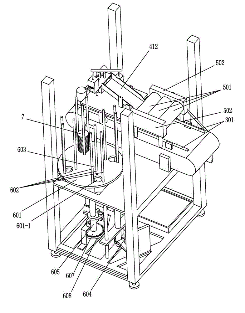
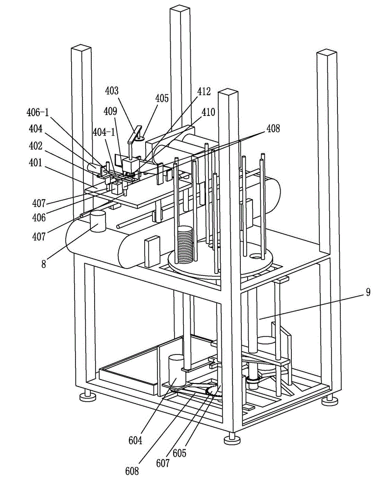
[0027] Described lifting device 9 is made up of lifting screw mandrel 901, lifting guide rod 902, lifting motor 903 and lifting guide plate 904, and lifting motor 903 is connected with runner 906 at the bottom end of lifting screw mandrel 901 by belt or chain 905, and lifting guide plate 904 Sleeved on the lifting screw rod 901, the two ends of the lifting guide plate 904 are guided and slidably connected with the two lifting guide rods 902, and the bottom end of the lifting mandrel 606 is fixedly connected to the lifting guide plate 904 through the connecting plate 907; the lifting guide plate 904 is connected by the lifting wire The positive rotation and reverse rotation of the rod 901 realizes up and down lifting, and the bottom end of the lifting jack 606 is connected with the lifting guide plate 904 through the connecting plate 907, so that the lifting guide plate 904 drives the lifting jack 606 to realize the up and down lifting. For the stability of the lifting device 9,...


PUM


Abstract

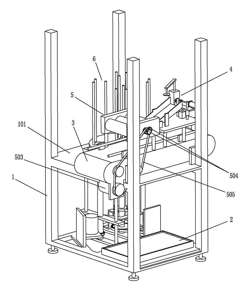
The invention relates to an automatic capping packaging machine which comprises a stand and an electronic control device, wherein a working platform is arranged on the stand; a conveying track is fixedly arranged on the working platform; a cover taking device and a capping device are respectively arranged above the conveying track along the direction of forward motion of the conveying track; and a cover storage device is arranged at one side (close to the cover taking device) of the conveying track. The automatic capping packaging machine is simple in working principle, simple and reasonable in mechanical structure and short in capping time, thus effectively improving the capping efficiency of bottle cans and reducing the production cost.

Description

technical field [0001] The invention relates to the technical field of packaging machinery, in particular to an automatic capping packaging machine with simple, reasonable and high efficiency. Background technique [0002] At present, the iron cans containing materials, such as milk powder cans, seasoning cans, etc., have an iron cover that is sealed and connected to the can body at one time for the opening. The plastic packaging cover, after the iron cover is opened once, is sealed twice by the plastic packaging cover, which plays the role of dustproof and waterproof, while the existing plastic packaging cover is generally set by manual cover, resulting in low production efficiency . Contents of the invention [0003] The purpose of the present invention is to solve the shortcomings of the above-mentioned prior art, and provide an automatic capping packaging machine with simple and reasonable structure and high production efficiency. [0004] The technical solution adop...

Claims


Application Information

Patent Timeline
Patent Type & Authority Applications(China)
IPC IPC(8): B67B3/00
Inventor 利建华
Owner 广州市利悦食品包装技术有限公司
Learn More