Novel steel truss concrete slab form support system

A technology of floor formwork and support system, which is applied in the field preparation of formwork/formwork/work frame, building components, construction, etc. It can solve the problems of affecting decoration, electromechanical installation, affecting the construction period, and high cost. The effect of shortening the construction period, saving the cost of construction measures, and reducing the input of manpower and material resources

Inactive Publication Date: 2012-10-10
CHINA CONSTR THIRD ENG BUREAU GRP CO LTD
View PDF6 Cites 2 Cited by
  • Summary
  • Abstract
  • Description
  • Claims
  • Application Information

AI Technical Summary

Problems solved by technology

However, when the height below the steel truss is large, the ordinary steel pipe scaffolding system cannot meet the force requirements, and it needs to be reinforced by lattice columns, which is expensive; Affect the progress of decoration, electromechanical installation and other processes in the lower floors, thus affecting the construction period of the entire project

Method used


Image

  • Novel steel truss concrete slab form support system
  • Novel steel truss concrete slab form support system

Examples


Embodiment Construction

[0015] Attached below Figure 1-2 The present invention is illustrated by way of example, but the specific embodiments are not intended to limit the present invention.

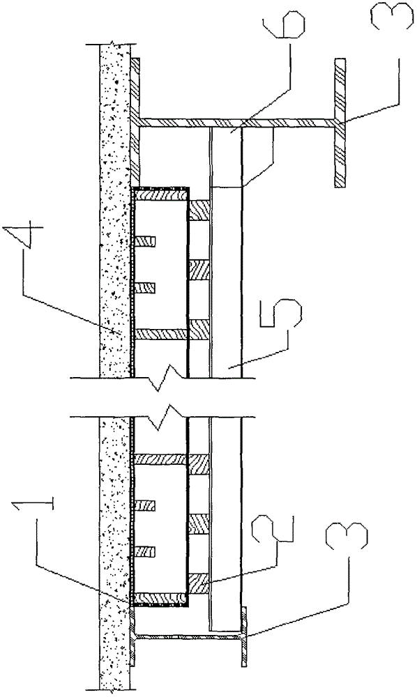
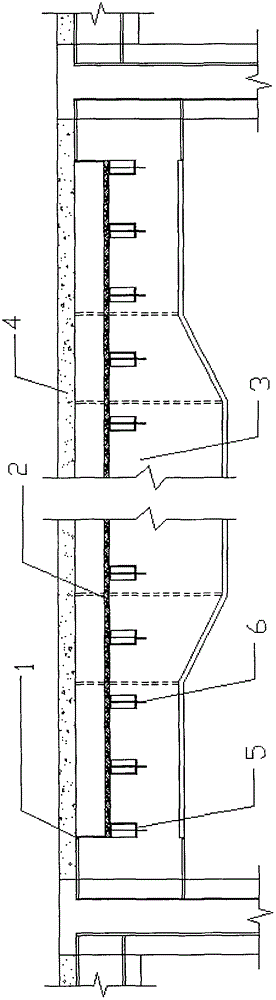
[0016] The new steel truss concrete floor formwork support system as shown in the figure includes steel truss beams 3, I-shaped steel keels 5, forming formwork boxes 1, square wooden beams 2, steel plate welding corbels 6, and concrete floors 4 to be poured. The I-shaped steel keel 5 is arranged between the steel truss beams 3 and used as the main load-bearing member of the supporting formwork, and the square wooden frame 2 is distributed vertically to the I-shaped steel keel 5 and a forming template box 1 is arranged on its upper part. The forming formwork box is used as the bottom mold of the concrete floor 4, and the steel plate welding corbel 6 is welded on the steel truss steel beam 3 as the support of the I-beam.

[0017] The specific implementation is as follows:

[0018] Weld the steel plate welding ...


PUM


Abstract

The invention discloses a novel steel truss concrete slab form support system which comprises steel truss shaped steel beams (3), an I-shaped steel keel (5), a forming template box (1), a square wooden column (2), steel plate welding corbel-pieces (6) and a to-be-poured concrete floor (4), wherein the I-shaped steel keel (5) is arranged between the steel truss shaped steel beams (3) and serves as a template supporting main keel; the square wooden column (2) is distributed in vertical to the I-shaped steel keel (5), and the forming template box (1) is arranged at the upper part of the square wooden column (2); the forming template box (1) serves as a concrete slab bottom form; and the steel plate welding corbel-pieces (6) are welded on the steel truss shaped steel beams (3). The novel steel truss concrete slab form support system provided by the invention has the advantages that the support system is simple to operate, the investment is reduced, and influence, which is caused by reinforcing a lower part floor, on others procedures of construction in the lower part floor can be avoided.

Description

technical field [0001] The present invention relates to a new type of floor formwork support system, in particular to a novel steel truss concrete floor formwork support system, and the invention also relates to the use of the system in steel truss concrete floor formwork and ordinary reinforced concrete floor formwork for other steel structure beams. The purpose of the support system. Background technique [0002] In the conventional concrete floor formwork support system, a full house scaffolding is generally set up on the lower floor as a support system for supporting the upper beam slab formwork. However, when the height below the steel truss is large, the ordinary steel pipe scaffolding system cannot meet the force requirements, and it needs to be reinforced by lattice columns, which is expensive; It will affect the progress of decoration, electromechanical installation and other processes in the lower floors, thereby affecting the construction period of the entire pro...

Claims


Application Information

Patent Timeline
Patent Type & Authority Applications(China)
IPC IPC(8): E04G11/36E04G11/48E04G11/50
Inventor 杜福祥任志平周佳军邓国辉陈国袁渊陈金伟董欢欢
Owner CHINA CONSTR THIRD ENG BUREAU GRP CO LTD
Why Eureka
Try Eureka