Weatherometer for solar cell plate

A technology for solar panels and test devices, applied in measurement devices, weather resistance/light resistance/corrosion resistance, instruments, etc., to achieve the effects of suppressing the deviation of luminous efficiency, reliable cooling, and simplified structure

Inactive Publication Date: 2012-10-10
USHIO DENKI KK
View PDF2 Cites 2 Cited by
  • Summary
  • Abstract
  • Description
  • Claims
  • Application Information

AI Technical Summary

Problems solved by technology

Inert gas discharge lamps are widely used for various purposes such as light sources such as sterilization devices, document lighting devices, and backlights. However, they are used as ...

Method used


Image

  • Weatherometer for solar cell plate
  • Weatherometer for solar cell plate
  • Weatherometer for solar cell plate

Examples


no. 1 approach

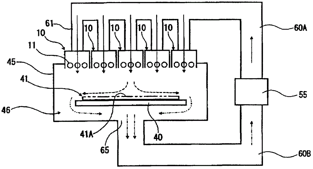
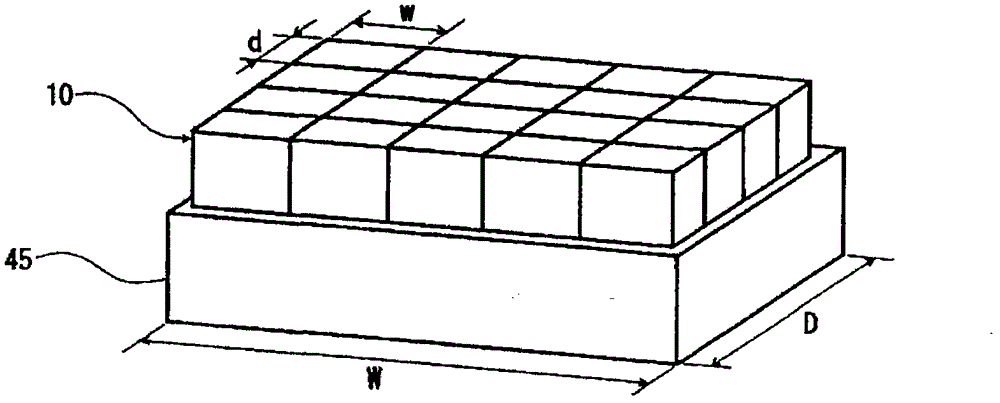
[0083] figure 2 It is an explanatory drawing which shows the outline of the structure of an example of the weather resistance test apparatus for solar cell panels which concerns on 1st Embodiment of this invention, image 3 It is a perspective view which shows an example of the arrangement|positioning example of the lamp unit in the weather resistance test apparatus for solar cell panels which concerns on 1st Embodiment of this invention.

[0084] This solar cell panel weather resistance test device (lower surface, referred to simply as "weather resistance test device") is equipped with a housing 45, which is a box-shaped rectangular parallelepiped as a whole, and has a predetermined ultraviolet irradiation device for solar cell panel 41 inside. In the processing chamber 46 for processing, the stage 40 made of, for example, stainless steel on which the solar cell panel 41 is mounted is arranged such that the workpiece mounting surface extends, for example, in the horizontal d...

no. 2 approach

[0108] Figure 5 It is an explanatory drawing which shows the outline of the structure of an example of the weather resistance test apparatus for solar cell panels concerning 2nd Embodiment of this invention.

[0109] This solar cell panel weather resistance test device (weather resistance test device) is equipped with a casing 45, and the overall casing 45 is a box shape of a cuboid, and a treatment chamber 46 for performing predetermined ultraviolet irradiation treatment on the solar cell panel 41 is formed inside it. Inside the processing chamber 46 is arranged a fixing member 48 that holds and fixes the solar cell panel 41 with its light irradiation surface 41A positioned in a vertical plane.

[0110]The fixing member 48 in this example is composed of a flat rectangular parallelepiped frame with upper and lower openings, and the solar cell panel 41 is slidably inserted into the upper and lower ends of each flat side surface, for example, the cross-sectional shape is L-shap...


PUM


Abstract

The invention provides a new-structure weatherometer for a solar cell plate to alleviate the deviation of the lighting efficiency of a plurality of inert gas discharging lamps respectively, and the solar cell panel is maintained in the specified temperature condition without generating nonuniform temperature. The weatherometer for the solar cell plate is provided with the plurality of rod-shaped inert gas discharging lamps, an air supply mechanism, and a temperature adjusting mechanism; the discharging lamps are configured to be oppositely arranged by separating from the light emitting surface of the solar cell panel, and the central shafts of every two adjacent inert gas discharging lamps extend in mutual parallel; the air supply mechanism supplies air to the light emitting surface of the solar cell panel through the gap between every two adjacent inert gas discharging lamps; and the temperature adjusting mechanism adjusts the temperature of the cooling air supplied by the air supply mechanism.

Description

technical field [0001] The present invention relates to a weather resistance test device for a solar cell panel that irradiates ultraviolet rays to, for example, a large-area solar cell panel. Background technique [0002] In recent years, from the viewpoint of protecting the global environment, clean energy that does not consume fossil fuels is being sought. Among them, solar cells capable of utilizing the solar energy that can be said to be infinite have attracted attention, and photovoltaic power generation systems and the like have been introduced and developed. The life characteristics of solar cells are as follows: the ultraviolet rays emitted by the sun have the greatest impact, and due to sunlight exposure, physical and chemical properties deteriorate, and the performance and functions of solar cells also deteriorate. Therefore, it is a very important factor in product design to understand in advance the state of deterioration due to, for example, sunlight exposure ...

Claims


Application Information

Patent Timeline
IPC IPC(8): G01N17/00
Inventor 三宅裕士田川幸治井口毅彦中岛敏博小田孝治
Owner USHIO DENKI KK
Why Eureka
Try Eureka