Pull head for zipper

A technology for zippers and sliders, applied in the field of sliders for zippers, which can solve problems such as discomfort, hooking of clothes or fibers, and tingling sensation, and achieve the effects of reduced damage, reduced wear, and easy installation

Active Publication Date: 2012-10-17
YKK CORP
View PDF5 Cites 5 Cited by
  • Summary
  • Abstract
  • Description
  • Claims
  • Application Information

AI Technical Summary

Problems solved by technology

However, when the zipper is installed, the zipper, especially the handle of the slider, will move freely, which will not only cause poor appearance, but also cause unpleasant sounds due to repeated contact between the body of the slider and the handle due to vibration. At the end of the operation, the handle and the slider are required to remain motionless in a certain posture
[0015] On the other hand, the above-mentioned patent documents 1 to 4 are all configured such that the handle can be engaged and disengaged from the clip or the slider body through the column, but the height of the column that engages and disengages with the left and right pair of cantilever locking pieces is too high, When fastening the handle to the column, it is necessary to insert a key into the through hole formed in the column to lock it. Therefore, the upper end of the column protrudes upward from the handle, and when it comes into contact with the human body or clothing Not only is there a tingling sensation, but there is also the undesirable situation of catching clothes or fibers

Method used


Image

  • Pull head for zipper
  • Pull head for zipper
  • Pull head for zipper

Examples


Embodiment Construction

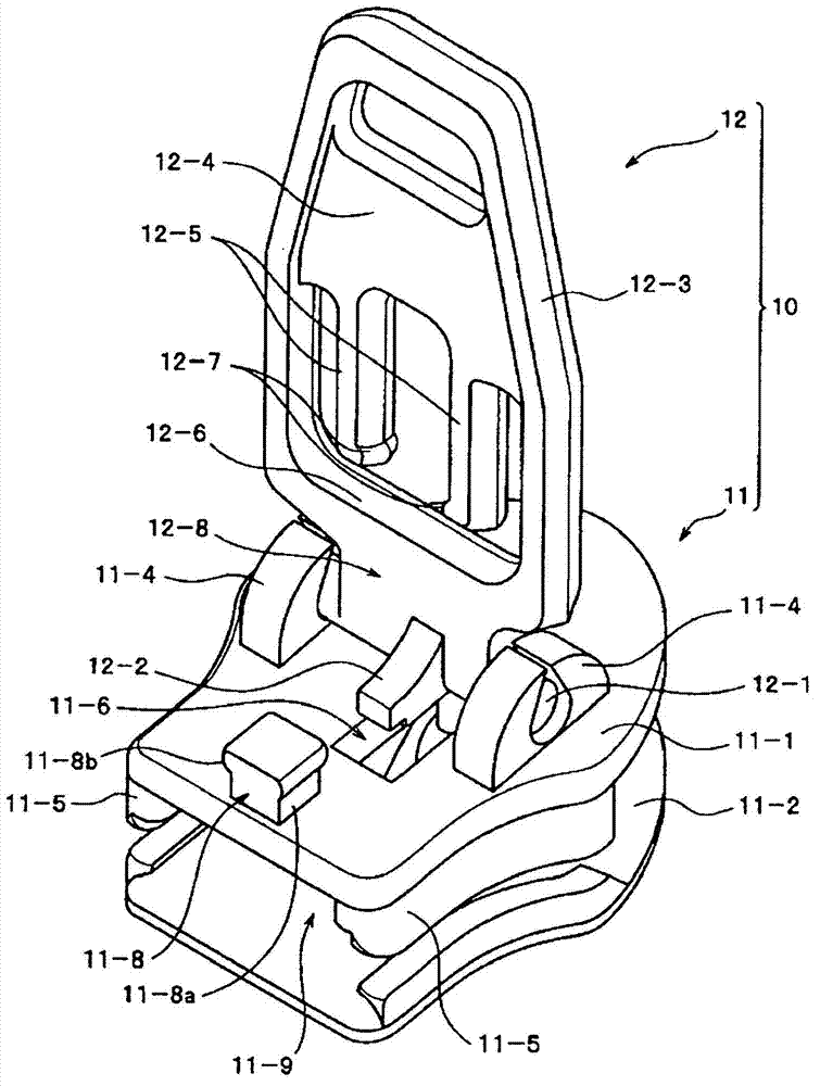
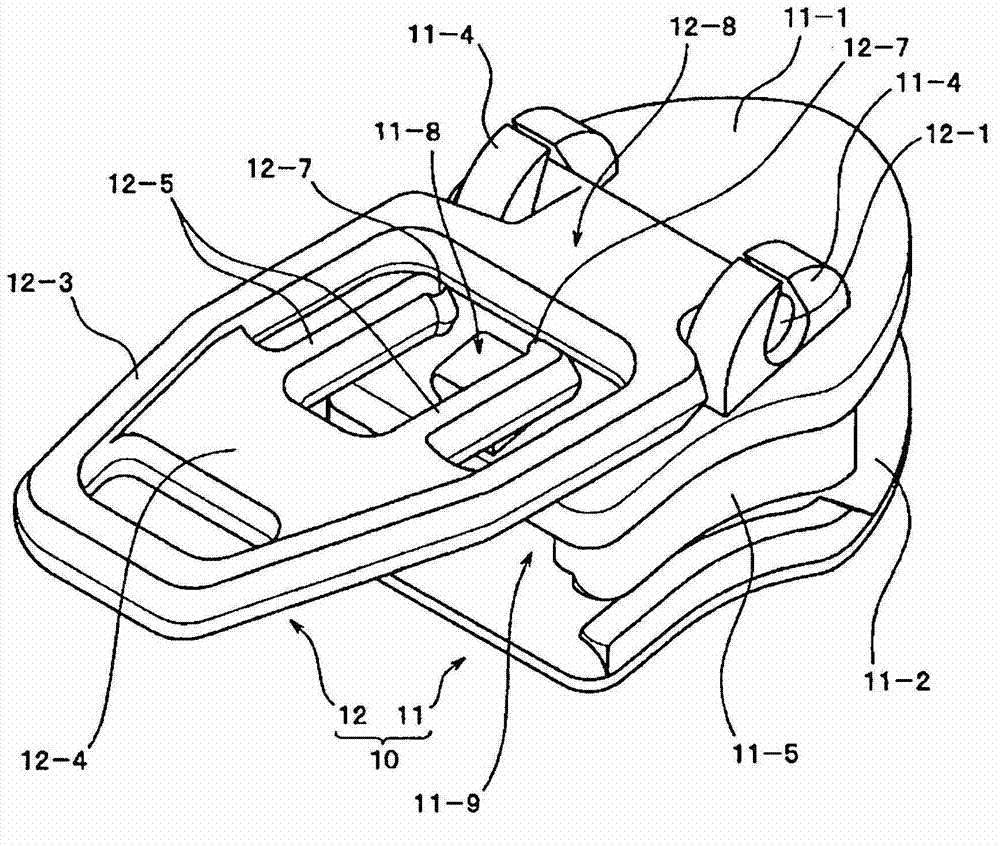
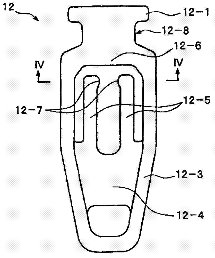
[0041] Next, preferred embodiments of the present invention will be described in more detail by way of examples based on the drawings. Figure 1~Figure 9 Shows the first embodiment of the present invention. figure 1 as well as figure 2 It is an external view of the slider 10 of the first embodiment. The slider 10 of the first embodiment is as figure 1 as well as Figure 6 As shown, it is composed of a slider body 11 and a handle 12 .

[0042] The slider body 11 has an upper wing plate 11-1 and a lower wing plate 11-2, and a connecting column 11-3 is used to connect the shoulder side ends of the upper wing plate 11-1 and the lower wing plate 11-2 at a predetermined interval. between. Pivot support portions 11-4 for pivotally supporting the rotation shaft 12-1 of the handle 12 are protrudingly provided on the left and right of the upper surface of the substantially central portion of the upper wing plate 11-1. Left and right flanges 11-5 extend toward the lower wing 11-2 ...


PUM


Abstract

The invention discloses a pull head for a zipper, comprising a handle clamping-releasing column part (11-8) projecting upwards from the upper surface of a pull head body (11), and a pair of suspension arm clamping-stopping sheets (12-5) formed on the window part of a handle (12), wherein the handle clamping-releasing column part (11-8) and the suspension arm clamping-stopping sheets (12-5) are clamped-combined via hasps. On the clamping-releasing parts of the above suspension arm clamping-stopping sheets (12-5) and the handle clamping-releasing column part (11-8), the head part receiving spaces (PS) used for receiving and clamping-stopping a clamping-releasing head part (11-8b) when the suspension arm clamping-stopping sheets (12-5) and the clamping-releasing head part (11-8b) are clamped-fixed. According to the composition, the clamping-releasing of the handle clamping-releasing column part (11-8) and the suspension arm clamping-stopping sheets (12-5) is easy to be conducted, and the suspension arm clamping-stopping sheets (12-5) of the handle are hard to be damaged, the discomfort caused by the projected end of the handle clamping-releasing column part or a fibre hook and the like are removed, and the pull head has durability.

Description

[0001] The patent application of the present invention is a divisional application of the invention patent application whose application number is 200880128781.5, the application date is April 23, 2008, and the invention name is "zipper slider". technical field [0002] The present invention relates to a slider for a slide fastener, which can releasably fix a handle to the upper surface of the slider in a fallen state when the slider is stopped, and can easily perform a stop operation of the slider and switching of a slide operation. Background technique [0003] In the past, as a mechanism for locking the slider in the closed state of the slide fastener, for example, such a card is disclosed in Japanese Patent Publication No. 44-21609 (Patent Document 1) or US Patent No. 2,569,076 (Patent Document 2). The locking device, that is, a locking protrusion is protrudingly provided on the upper surface of the upper locking member, and a locking hole is formed through the locking pr...

Claims


Application Information

Patent Timeline
IPC IPC(8): A44B19/30
Inventor 槻庆一武秀哉
Owner YKK CORP
Why Eureka
Try Eureka