
Capon operation table

An operating table and capon technology, which is applied in the field of capon operating tables, can solve the problems of large size, inconvenient portability, operation, assembly and disassembly of the operating table, and achieves high operation efficiency, good economic and social benefits, portability and convenience. Easy-to-use effects

Inactive Publication Date: 2012-10-17
王磊
View PDF3 Cites 7 Cited by
  • Summary
  • Abstract
  • Description
  • Claims
  • Application Information

AI Technical Summary

Problems solved by technology

The existing problem is that the operating table is bulky and inconvenient to carry, operate, assemble and disassemble.

Method used


Image

  • Capon operation table
  • Capon operation table
  • Capon operation table

Examples


Embodiment 1

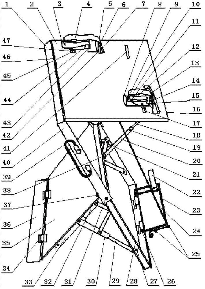
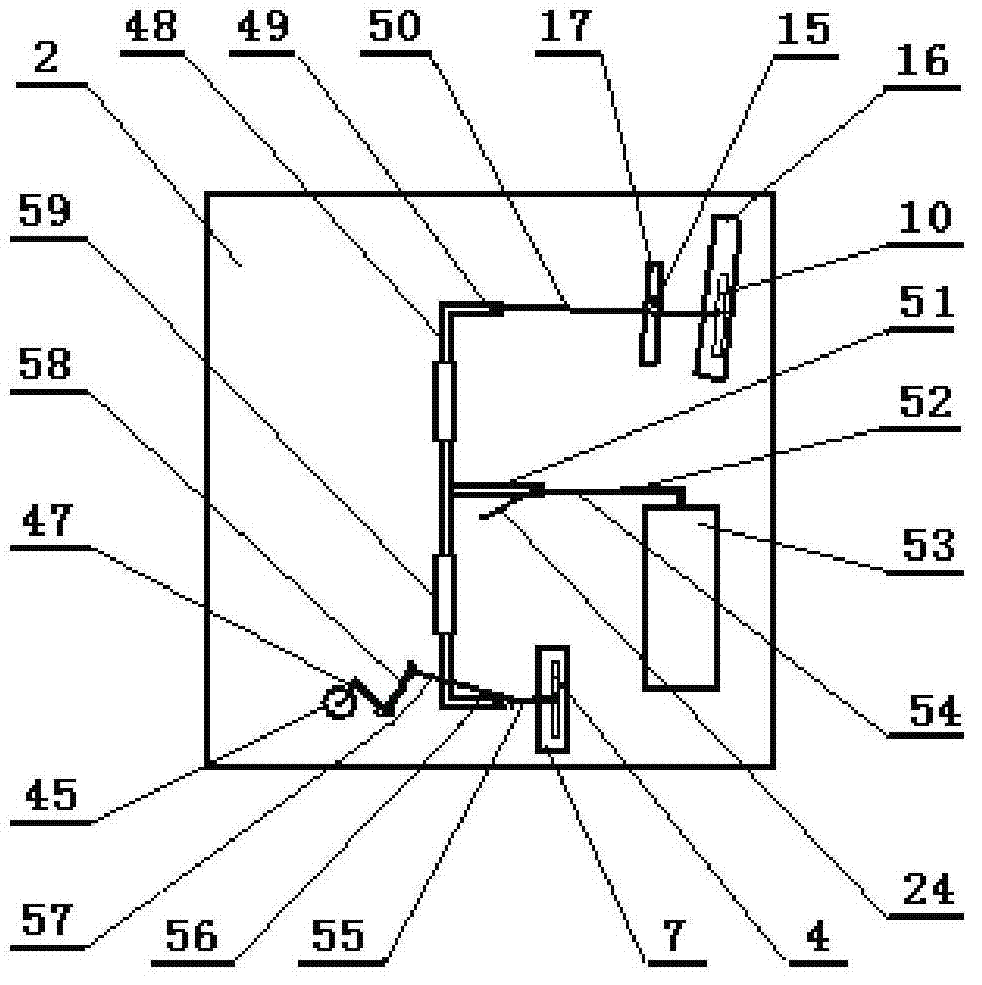
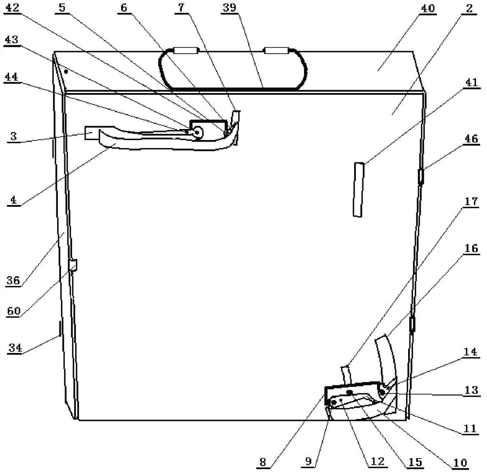
[0029]The capon operating table of this example, its structure includes setting platen 2 and telescopic supporting frame 1, and described platen 2 is provided with counting hole 41, fixed large clamp, fixed small clamp, large upper clamp movable hole 7, large lower clamp pull wire Hole 45, small upper clamp displacement movable hole 16, small clamp fixed displacement slot 17; described fixed large clamp and fixed small clamp are respectively located on the surface close to the platen 2 corresponding to both sides of the platen 2, and the fixed large clamp The clamp is fixed on the platen 2 by the large clamp fixing seat 42, and the small clamp is fixed on the platen 2 by the small clamp fixing seat 8 through the small clamp fixing bolt 15 on the platen 2 of the small clamp fixing displacement slot 17; the platen 2 adopts a platform The board leaflet 46 is connected with the supporting frame 1 . Among them, the large fixed clamp is provided with a large upper clamp 4, a large u...

Embodiment 2

[0037] The capon operating table of this example, its structure includes setting platen 2 and telescopic supporting frame 1, and described platen 2 is provided with counting hole 41, fixed large clamp, fixed small clamp, large upper clamp movable hole 7, large lower clamp pull wire Hole 45, small upper clamp displacement movable hole 16, small clamp fixed displacement slot 17; described fixed large clamp and fixed small clamp are respectively located on the surface close to the platen 2 corresponding to both sides of the platen 2, and the fixed large clamp The clamp is fixed on the platen 2 by the large clamp fixing seat 42, and the small clamp is fixed on the platen 2 by the small clamp fixing seat 8 through the small clamp fixing bolt 15 on the platen 2 of the small clamp fixing displacement slot 17; the platen 2 adopts a platform The board leaflet 46 is connected with the supporting frame 1 . Among them, the large fixed clamp is provided with a large upper clamp 4, a large ...


PUM


Abstract

The invention discloses a capon operation table which comprises a table plate and a telescopic supporting frame, wherein the table plate is provided with a counting hole, fixed big clips, fixed small clips, a big upper clip moving hole, a big lower clip moving hole, a big lower clip pull wire hole, a small upper clip shifting activity slotted hole and a small clip fixing shifting slotted hole; and a main pull wire pedal rack drives a main pull wire to pull a main pull wire rod, a counter pull rod, a small upper clip pull wire rod and a big upper clip pull wire rod to operate a small upper clip, a big lower clip and a big upper clip of the table plate, so that the fixed big clips and the fixed small clips open or close simultaneously. When the capon operation table is not used, telescopic rod fixing bolts are loosened, the supporting frame, the table plate and a supporting plate are pushed and pressed, so that the capon operation table is placed and carried conveniently. The capon operation table is simple in structure, easy to assemble and disassemble, small in size, convenient to carry and use, easy to operate, high in efficiency, safe and reliable, can be used for castrating a large batch of chickens, is safe and effective for henneries and rural capon operators, and has high economic benefits and social benefits.

Description

technical field [0001] The invention belongs to capon surgical tools, and relates to a capon operating table. Background technique [0002] In chicken breeding, in order to avoid feed consumption caused by roosters fighting, shorten the breeding time for growth, improve meat quality, and increase benefits, the traditional method is to use small roosters weighing about 0.5 kg (over 2.5 weeks old) as Castration surgery removes the cockerels. In recent years, people have also adopted castration surgery on pullets. After castration, due to the decrease in estrogen secretion and increased meat production, the meat quality is more juicy, the meat is fresh and tender, and the taste of the meat is improved. In addition, it will also be "transsexual" in appearance, with some characteristics of roosters. This kind of hen also crows and has bright feathers. Capon meat is tender and nutritious. According to the micro-analysis of Guangxi Analysis, Testing and Research Center, the high...

Claims


Application Information

Patent Timeline
IPC IPC(8): A61D3/00
Inventor 王磊
Owner 王磊
Learn More