Clear water controlling device for high-energy mixer and high-energy mixer

A technology of a control device and a mixer, which is applied to the mixed operation control device, mixed operation control, fluid state mixer, etc., can solve the problems of instability of the hydraulic system, many internal structural parts, and easy freezing of the sealing surface. The movement structure is simple and flexible, meets the requirements of use, and has excellent mixing effect.

Active Publication Date: 2012-10-17
YANTAI JEREH PETROLEUM EQUIP & TECH CO LTD
View PDF3 Cites 108 Cited by
  • Summary
  • Abstract
  • Description
  • Claims
  • Application Information

AI Technical Summary

Problems solved by technology

[0003] At present, most of the clear water control mechanisms of double-variable high-energy mixers at home and abroad adopt a hydraulic drive method. For example, the high-energy mixer disclosed in Chinese patent CN 200620095469 belongs to this kind of double-variable mixer scheme. This type of control method uses a flow regulating plate structure to control the water volume. Although it has made great progress compared with manual control, there are still the following defects: First, due to the hydraulic drive mode, it is greatly affected by the ambient temperature an...

Method used


Image

  • Clear water controlling device for high-energy mixer and high-energy mixer
  • Clear water controlling device for high-energy mixer and high-energy mixer
  • Clear water controlling device for high-energy mixer and high-energy mixer

Examples


Embodiment Construction

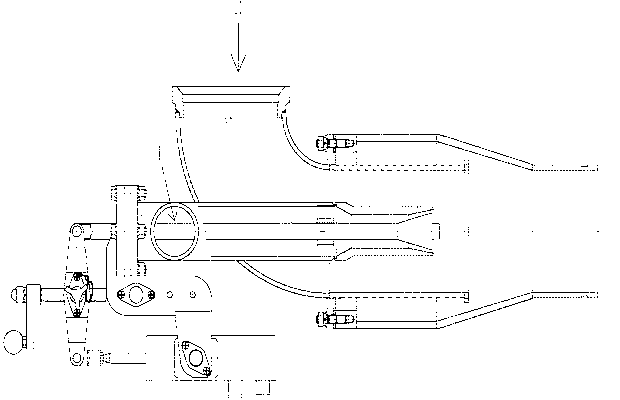
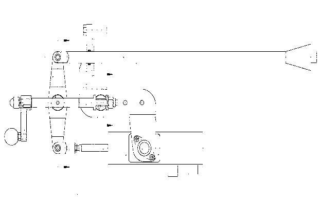
[0023] like Figure 1-Figure 5 As shown, a clean water control device for a high-energy mixer includes a mounting base 1, a shaft 2, a linear actuator 3, a hinge shaft 4, a lead screw 5, a threaded shaft 6, a manual crank 7, a rocker arm 8, a valve stem 9, The pin shaft 10 and the fixing seat 12 are characterized in that: the upper part of the mounting seat 1 is equipped with a flange, and is fixedly connected with the end flange of the clear water pipe 13 of the high-energy mixer, and the lower end of the mounting seat 1 and the There are shaft holes in the middle, and the hinge shaft 4 is inserted into the middle shaft hole of the mounting seat 1. The linear actuator 3 is equipped with a fixing seat 12, and shafts 2 are arranged on both sides of the fixing seat 12. , the shaft 2 is inserted into the shaft hole at the lower end of the mounting base 1 .

[0024] The middle part and both ends of the rocker arm 8 are provided with shaft holes, the upper end of the rocker arm 8 ...


PUM


Abstract

The invention relates to cementing equipment and mixing equipment for oil and gas field and provides a clear water controlling device for a high-energy mixer and the high-energy mixer. The clear water controlling device comprises a soleplate, a linear actuator, a hinge shaft, a rocking arm, a leading screw, a manual rocking handle, a thread spindle and a valve rod, and is characterized in that the soleplate is hinged with a mounting base of the linear actuator; the hinge shaft is inserted in a central shaft hole of the soleplate; one end of the leading screw is fixed on the hinge shaft; the central portion of the leading screw forms a sleeve joint with the thread spindle, which is inserted in a central hole of the rocking arm; the upper end of the rocking arm is hinged with the valve rod; the lower end of the rocking arm is hinged with a push rod of the linear actuator; a through hole is arranged at the junction of the thread spindle and the leading screw; and a pin is disposed inside the trough hole. According to the invention, automatic and accurate control of the valve rod feed can be conveniently realized such that the slurry mixing effect of the high-energy mixer is more excellent than that in the prior art and the high-energy mixer can be used in both automatic and manual modes.

Description

technical field [0001] The invention relates to a high-energy mixer for cementing equipment and mud-mixing equipment used in oil and gas fields, in particular to a high-energy mixer clear water control device and a high-energy mixer. Background technique [0002] In the process of cementing operations in oil and gas fields, there are strict requirements on the control of cement slurry density. As one of the core components of cementing equipment, the high-energy mixer is directly related to the cementing quality. The traditional single-variable high-energy mixer that uses manual valves to control the flow of clean water is completed by the operator adjusting the size of the valve. The flow of clean water can only be adjusted based on the experience and intuition of the operator, so it is difficult to ensure the density of the cement slurry. And because the fluctuation of cement slurry density may affect the quality of cementing, which in turn will affect the productivity of ...

Claims


Application Information

Patent Timeline
IPC IPC(8): B28C7/00
CPCB01F5/0461B28C7/12B01F25/3133
Inventor 王锋李世奇
Owner YANTAI JEREH PETROLEUM EQUIP & TECH CO LTD
Why Eureka
Try Eureka