Tank tidying device for continuous sterilization machine

A sterilizer and can unscrambling technology, applied in packaging sterilization, conveyor objects, transportation and packaging, etc., can solve the difficulty of meeting the requirements of continuous sterilization and mass production, and increase the difficulty and labor intensity of subsequent processes , the straightening out of the tank body and the insufficient smoothness of the conveying, etc., to achieve the effect of simple structure, satisfying continuity and mass production, and good protection

Active Publication Date: 2012-10-17
山东鼎泰盛机械科技有限公司
View PDF6 Cites 3 Cited by
  • Summary
  • Abstract
  • Description
  • Claims
  • Application Information

AI Technical Summary

Problems solved by technology

[0002] After the continuous sterilizer performs secondary sterilization on the tanks filled with food, beverages or pharmaceuticals, the tanks need to be output for subsequent processing after cooling down in the water tank. Due to the continuity and large-scale nature of continuous sterilization , so the number of tanks in the water tank is extremely large and is in an irregular scattered state. If the water tank is output in the above state for subsequent processing, it will greatly increase the processing difficulty and labor intensity of the subsequent process, and the efficiency is low. Therefore, it is necessary to The tanks in the loose state are straightened out and output to the water tank to facilitate the processing of subsequent processes and improve production efficiency
However, most of the existing can unscrambling equipment for straightening tanks is not reasonable in structure, the tank processing capacity is insufficient, the straightening and transportation of tanks are not smooth enough, and it is difficult to meet the continuity of continuous sterilization and the requirements of mass production , reducing production efficiency

Method used


Image

  • Tank tidying device for continuous sterilization machine
  • Tank tidying device for continuous sterilization machine
  • Tank tidying device for continuous sterilization machine

Examples


Embodiment Construction

[0016] Below in conjunction with accompanying drawing and embodiment, further elaborate the present invention. In the following detailed description, certain exemplary embodiments of the invention are described by way of illustration only. Needless to say, those skilled in the art would realize that the described embodiments can be modified in various different ways, all without departing from the spirit and scope of the present invention. Accordingly, the drawings and description are illustrative in nature and not intended to limit the scope of the claims.

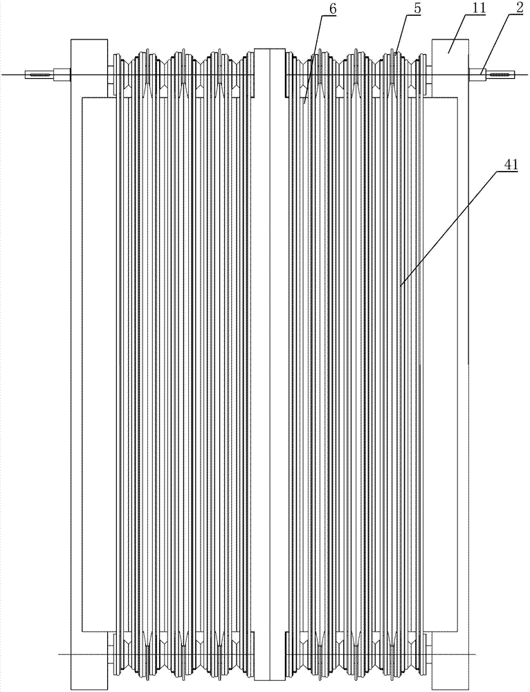
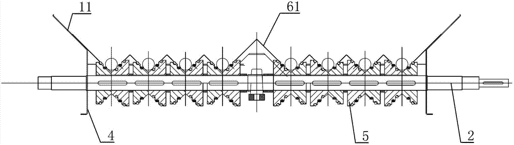
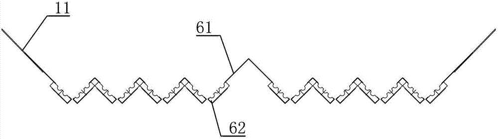
[0017] Such as figure 1 As shown, the can unscrambling device for a continuous sterilizer includes a bracket 1, and the bracket 1 is rotated to be provided with a driving shaft 2 and a driven shaft 3, and the driving shaft 2 and the driven shaft 3 are respectively arranged with corresponding conveying shafts. Pulley 5, the outer peripheral surface of the conveyor pulley is provided with a V-shaped ring groove, and the d...


PUM


Abstract

The invention discloses a tank tidying device for a continuous sterilization machine. The tank tidying device comprises a support, a driving shaft and a driven shaft are rotatablely arranged on the support; mutually corresponding conveyor belt wheels are arranged on the driving shaft and the driven shaft respectively; V-shaped ring grooves are formed on the outer peripheral surfaces of the conveyor belt wheels; tank tidying conveyor belts are in transmission connection between the corresponding conveyor belt wheels on the driving shaft and the driven shaft; V-shaped conveyor troughs matched with the ring grooves are arranged between the corresponding conveyor belt wheels on the driving shaft and the driven shaft; the tank tidying conveyor belts pass through the conveyor troughs and are sleeved on the inner side walls of the ring grooves; and the driving shaft is in transmission connection with a tank tidying power device. The tan tidying device is reasonable in structure, the tank body processing capacity is strong, and the tidying and conveying of a tank body are performed smoothly, so that the tank tidying device can meet requirements on continuous and mass production.

Description

technical field [0001] The invention relates to the technical field of light industry machinery, in particular to a can unscrambling device for a continuous sterilizer used for sorting tank bodies on a continuous sterilizer in industries such as filling food, beverages or pharmaceuticals. Background technique [0002] After the continuous sterilizer performs secondary sterilization on the tanks filled with food, beverages or pharmaceuticals, the tanks need to be output for subsequent processing after cooling down in the water tank. Due to the continuity and large-scale nature of continuous sterilization , so the number of tanks in the water tank is extremely large and is in an irregular scattered state. If the water tank is output in the above state for subsequent processing, it will greatly increase the processing difficulty and labor intensity of the subsequent process, and the efficiency is low. Therefore, it is necessary to The tanks in the loose state are straightened o...

Claims


Application Information

Patent Timeline
Patent Type & Authority Applications(China)
IPC IPC(8): B65B55/02B65G47/28
Inventor 姜伟
Owner 山东鼎泰盛机械科技有限公司
Why Eureka
Try Eureka