Engine type generator

A generator and engine type technology, applied in engine components, engine cooling, machine/engine, etc., can solve the problems of inconvenient handling, increase in the whole generator, increase the height of the whole machine, etc., to solve the problem of rotation and placement, The effect of saving material cost and improving reliability

Inactive Publication Date: 2012-10-17
CHONGQING RATO POWER
View PDF8 Cites 7 Cited by
  • Summary
  • Abstract
  • Description
  • Claims
  • Application Information

AI Technical Summary

Problems solved by technology

However, due to the limitation of the design of the patent, the length of the pivoting arm can only be increased towards the height of the generator, which will inevitably increase the height of the whole machine
At the same time, since the second fixed handle and the rotating shaft of the handle are fixed on the wall-shaped vertical frame made of resin, and the wall-shaped vertical frame also supports the central frame, if sufficient strength is to be ensured, the wall-shaped vertical frame must be made Strong enough, so you need to increase the amount of resin and increase the cost
Also, it is possible that such resin parts will not be sufficiently guaranteed in terms of strength
In addition, since the first and second fixed handles in this patent may not be set at the same horizontal position, as far as two people operate and carry them, their force points are not on the same horizontal line, which is inconvenient to carry
[0003] In addition, the fuel tank of the traditional silent engine generator is directly installed on the upper part of the crankcase of the engine. Due to the consideration of the fuel capacity, the fuel tank will be relatively large, and the horizontal expansion space at this position is limited, so the fuel tank will be in height. increase, resulting in an increase in the height of the generator

Method used


Image

  • Engine type generator
  • Engine type generator
  • Engine type generator

Examples


Embodiment Construction

[0036] Next, an engine generator according to an embodiment of the present invention will be described with reference to the accompanying drawings. The orientation referred to in the description, with figure 1 The orientation indicated in is the reference.

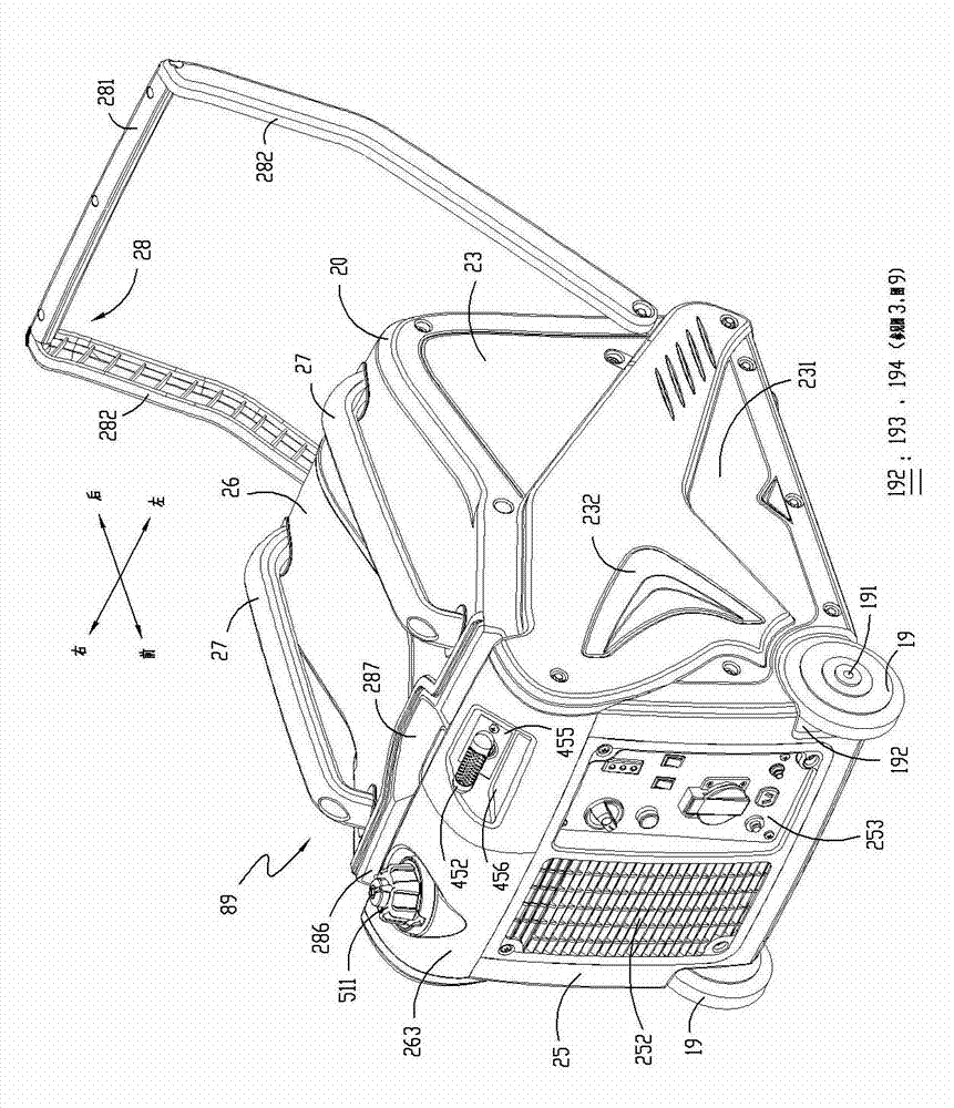
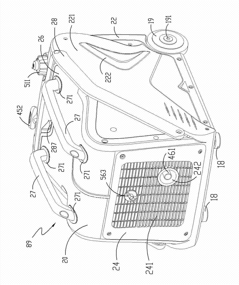
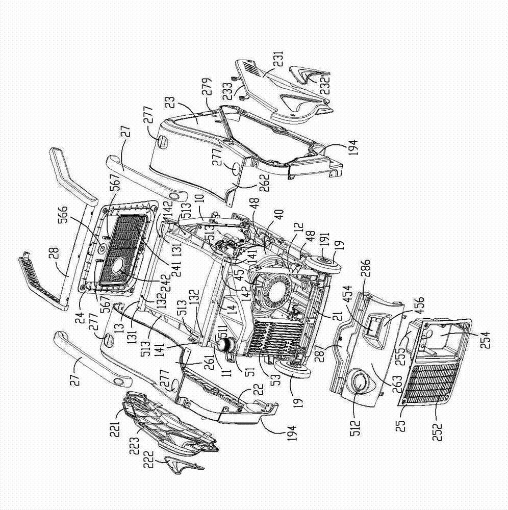
[0037] Such as Figure 1 to Figure 4 As shown, the engine generator 89 includes: a casing 20, which is approximately cuboid, and is composed of a right wall portion 22, a left wall portion 23, a rear wall portion 24, a front wall portion 25, a top wall portion 26 and a bottom plate 21, and the inner support There is a frame 10; a pair of wheels 19 are arranged on both sides of the front end at the bottom of the cabinet 20 to be set as moving parts of the cabinet 20 through a wheel shaft 191, and a pair of legs 18 and wheels 19 are arranged on both sides of the bottom of the cabinet 20 opposite to the wheels 19. Cooperate with the pull bar 28 that can pull the engine generator 89 to move, the legs 18 and the wheels 19 mak...


PUM


Abstract

The invention aims to provide an engine type generator, which is reliable and convenient for carrying and moving in a labor-saving way and is used for reinforcing an entire machine. The engine type generator comprises an engine, a chassis and a pull rod, wherein the generator is driven by using the engine; two wheels are set as movable pieces of the chassis; the pull rod is used for driving the generator to move in cooperation with the wheels; and a frame is arranged in the chassis.

Description

technical field [0001] The field of the invention relates to engine generators, in particular to box-type silent generators. Background technique [0002] The Chinese patent application with the publication number CN101614155A discloses an engine-driven generator, wherein the engine and the generator are accommodated in a housing. The engine-driven generator is provided with first and second fixed handles on the front and rear sides of the housing and a handle that swings vertically relative to the second fixed handle, that is, a movable handle. By lifting the first and second fixed handles or The generator can be moved and transported by one person lifting the handle. And because the handle is designed to swing vertically around the second fixed handle, the most effective arrangement is that the second fixed handle is arranged at the upper end of one side of the generator, and the length of the pivoting arm of the handle is at most the height of the generator. Only in...

Claims


Application Information

Patent Timeline
Patent Type & Authority Applications(China)
IPC IPC(8): F02B63/04F02B77/00F01P5/06F01N13/00F02N3/00
Inventor 杨佺杨希波
Owner CHONGQING RATO POWER
Why Eureka
Try Eureka