Hydraulic control device of automatic transmission

A technology of automatic transmission and control device, applied in the direction of transmission device control, elements with teeth, belt/chain/gear, etc., can solve the problems of increase, complicated cost of hydraulic control device, etc. The effect of increasing inhibition of

Inactive Publication Date: 2012-10-17
MAZDA MOTOR CORP
View PDF9 Cites 11 Cited by
  • Summary
  • Abstract
  • Description
  • Claims
  • Application Information

AI Technical Summary

Problems solved by technology

This will lead to the complexity and cost increase of the hydraulic control device

Method used


Image

  • Hydraulic control device of automatic transmission
  • Hydraulic control device of automatic transmission
  • Hydraulic control device of automatic transmission

Examples


Embodiment Construction

[0029] Embodiments of the present invention will be described below.

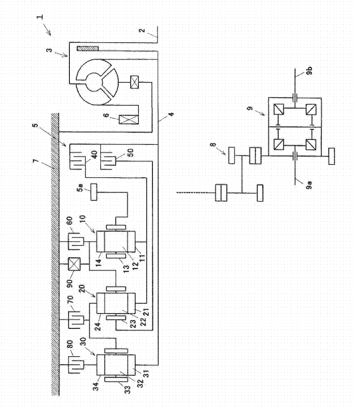
[0030] figure 1 It is a schematic diagram showing the structure of the automatic transmission 1 according to the embodiment of the present invention. This automatic transmission 1 is mounted on a transverse engine vehicle such as a front engine front drive vehicle. The automatic transmission 1 has a torque converter 3 attached to an engine output shaft 2 , a speed change mechanism 5 for inputting a rotational output of the torque converter 3 via an input shaft 4 , and an engine output shaft 2 via the torque converter 3 . The driven oil pump 6 is used as its main structural element. The torque converter 3 , the transmission mechanism 5 and the oil pump 6 are accommodated in a transmission case 7 . The rotational output of the transmission mechanism 5 is transmitted from the output gear 5a to the differential device 9 via the intermediate shaft drive mechanism 8 to drive the left and right axles 9a, 9b.

...


PUM


Abstract

A hydraulic control device of an automatic transmission is provided, which includes a hydraulic control circuit with a pressure reducing valve including a first friction element for achieving a first gear position and a second friction element for achieving a second gear position that produces a lower speed than the first gear position. The hydraulic control circuit further includes a switch valve formed with an input port which is inputted with the line pressure in a forward gear position range, and which is switched between a first state where the input port communicates with a first oil path communicating with the first friction element in a failure state of power distribution to the plurality of hydraulic control valves, and a second state where the input port communicates with the second friction element in the same power distribution failure state. The switch valve includes various control ports to control its function.

Description

technical field [0001] The present invention relates to a hydraulic control device of an automatic transmission mounted on a vehicle, especially the control of a solenoid valve for hydraulic control when power fails, and belongs to the technical field of automatic transmissions for vehicles. Background technique [0002] An automatic transmission mounted on a vehicle selectively engages a plurality of friction elements according to an operating state to automatically switch gears. The automatic transmission includes a hydraulic control device for controlling engagement of the friction elements. The hydraulic control device is provided with a switching valve for switching oil passages leading to each friction element, a hydraulic control valve for controlling engagement hydraulic pressure supplied to each friction element, and the like. Several of the valves consist of solenoid valves. The solenoid valve works according to the electric signal from the controller, and perfor...

Claims


Application Information

Patent Timeline
Patent Type & Authority Applications(China)
IPC IPC(8): F16H61/12
CPCF16H2061/126F16H61/686F16H61/12F16H61/68F16H61/40F16H61/4192
Inventor 佐治恒士郎镰田真也永井祥太郎
Owner MAZDA MOTOR CORP
Why Eureka
Try Eureka