
Device for detecting service life of valve core of water nozzle

A detection device and faucet technology, which is used in measuring devices, testing of mechanical parts, testing of machine/structural parts, etc., can solve the problems of not being able to test the life of the faucet handle, affecting the accuracy of test data, etc., and achieving cost-effectiveness High, compact structure, good rigidity

Inactive Publication Date: 2012-10-17
福建闽机机械科技有限公司
View PDF6 Cites 7 Cited by
  • Summary
  • Abstract
  • Description
  • Claims
  • Application Information

AI Technical Summary

Problems solved by technology

The patent uses the actuator to control the swing of the handle connecting rod (used to connect with the handle of the faucet) of the faucet valve core to control the water discharge of the faucet. Since the handle connecting rods of different models of single-handle and double-control faucets are basically the same, the testing machine It can be applied to different types of single-handle double-control faucets, and has strong versatility. However, the actuator is connected to the handle connecting rod of the faucet valve core instead of the handle of the faucet, which causes the test force of the handle connecting rod to be different from that of the faucet. Different forces in actual use will inevitably affect the accuracy of the test data, and only by operating the handle of the faucet can the life of the faucet valve core be accurately tested. In addition, this testing machine cannot test the life of the valve core at the same time. It can also test the life of the faucet handle

Method used


Image

  • Device for detecting service life of valve core of water nozzle
  • Device for detecting service life of valve core of water nozzle
  • Device for detecting service life of valve core of water nozzle

Examples


Embodiment 1

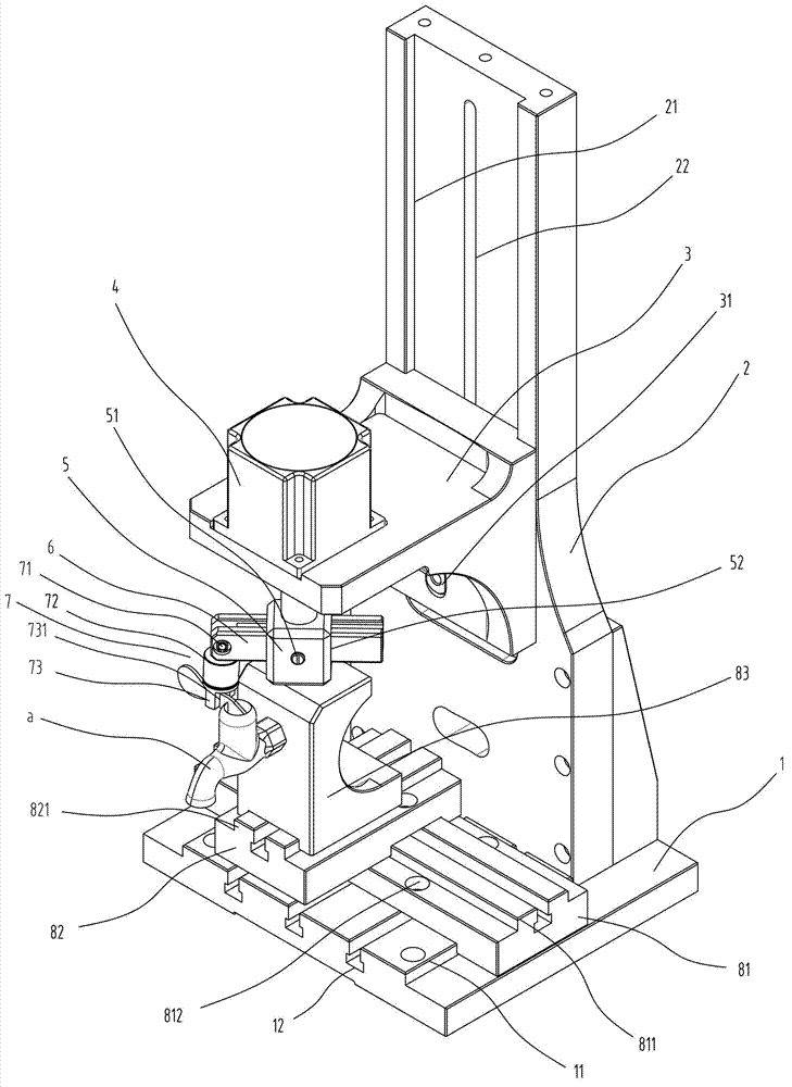
[0026] Embodiment one, with reference to figure 1 As shown, the universal faucet spool life detection device suitable for single-handle single-control faucet a includes a base 1, a column 2 set on the base 1, and a faucet that can be adjusted in the X and Y axis directions on the base 1 The positioning mechanism of the faucet, the sliding seat 3 arranged on the column 1 that can be moved up and down vertically, the motor 4 vertically installed on the sliding seat 3, and the horizontally penetrating guide hole 52 formed at the lower end of the output shaft of the motor 4 The rotary member 5, the swing rod 6 that is movable through the guide hole 52 of the rotary member 5, the locking bolt 51 that can lock or release the swing rod 6 on the rotary member 5, and the one end of the swing rod 6 that can be connected with The clamp 7 that the faucet handle matches.

[0027] A vertically extending Z-axis guide rail 21 is formed on the column 1. The slide seat 3 is movably arranged on...

Embodiment 2

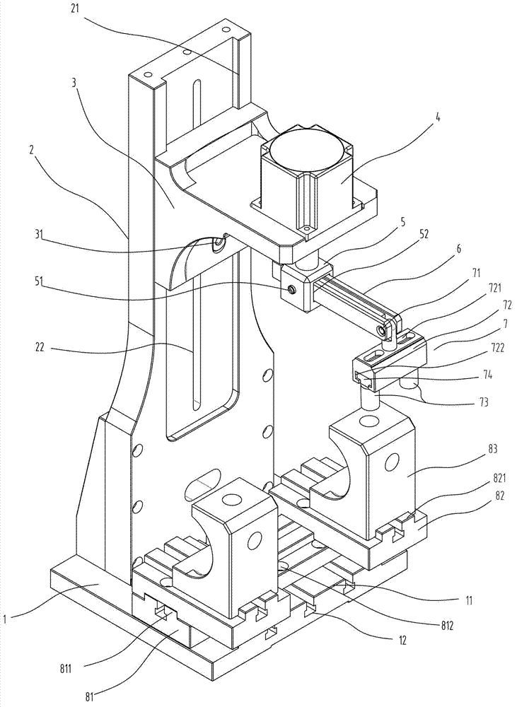
[0031] Embodiment two, refer to figure 2 As shown, the universal faucet spool life detection device suitable for single-handle double-control kitchen faucet is used to simulate the faucet to swing the faucet outlet pipe under manual operation to switch the water supply tank. Its main structure is the same as that of Embodiment 1. The main difference is: the faucet positioning mechanism and the 7 parts of the fixture. In order to adapt to the cold and hot water supply of the single-handle double-control kitchen faucet, two faucet mounting seats 83 for fixing the cold and hot water inlet ends need to be provided. The specific faucet positioning Two upper carriages 82 are movable on the X-axis guide rail 811 of the mechanism, and the second Y-axis guide rail 821 is formed on the two upper carriages 82 respectively, and the two nozzle mounting seats 83 are correspondingly arranged on the two upper carriages 82. on the second Y-axis guide rail 821 .

[0032] The clamp 7 includes ...

Embodiment 3

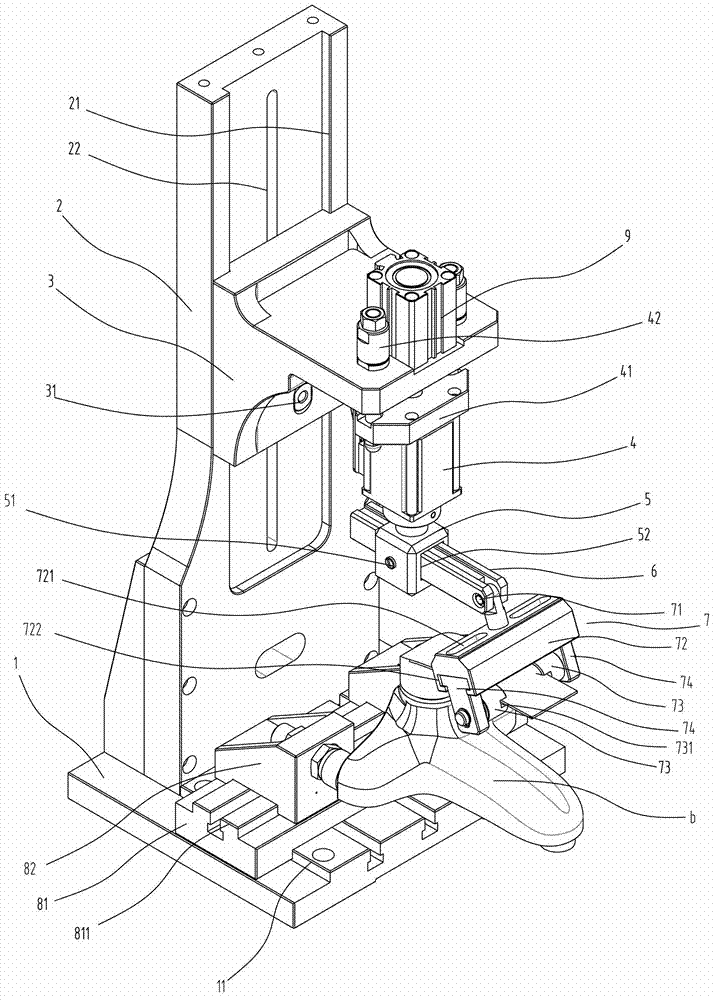
[0034] Embodiment three, refer to image 3 As shown, the universal faucet spool life detection device suitable for single-handle double-control faucet b is used to simulate the adjustment of the cold and hot water ratio and the water outlet switch control of the faucet under manual operation, including base 1, set on base 1 The column 2 on the top, the nozzle positioning mechanism that is set on the base 1 and can adjust the position of the nozzle in the X and Y axis directions, the sliding seat 3 that can be vertically moved up and down and adjusted on the column 1, and the vertical setting on the sliding seat 3 The cylinder 9, the motor mounting seat 41 connected to the lower end of the piston rod of the cylinder 9, the guide column 42 arranged between the motor mounting seat 41 and the sliding seat 3, the motor 4 vertically installed on the motor mounting seat 41, the motor mounting seat 41 arranged on the motor 4 The lower end of the output shaft is formed with a rotating ...


PUM


Abstract

The invention discloses a device for detecting the service life of a valve core of a water nozzle. The device comprises a base, a vertical column, a water nozzle positioning mechanism, a sliding base, a motor, a rotary piece, a swinging rod, a locking bolt and a clamp, wherein the vertical column is arranged on the base; the water nozzle positioning mechanism is arranged on the base and can be used for adjusting the position of the water nozzle in the X-axis and Y-axis directions; the sliding base is arranged on the vertical column in a mode of being adjusted by moving up and down vertically; the motor is arranged on the sliding base; the rotary piece is arranged at the lower end of an output shaft of the motor and is provided with a guide hole perpendicular to the output shaft of the motor; the swinging rod movably penetrates through the swinging rod in the guide hole of the rotary piece; the locking bolt is arranged on the rotary piece and can be used for locking or releasing the swinging rod; and the clamp is arranged at one end of the swinging rod and can be matched with a handle of the water nozzle or a water outlet pipe of the water nozzle. The device has the advantages of compact structure, reasonable arrangement, adjustment convenience, high automation degree, good rigidness, high generality and softness, high cost performance and the like.

Description

technical field [0001] The invention relates to a device for detecting the life of a faucet valve core, which is applicable to the life detection of various types of valve cores of a certain faucet product. Background technique [0002] There are two main ways to operate the faucet, one is to control the water output of the faucet by rotating the handle of the faucet, such as single-handle single-control faucet, double-handle double-control faucet, and the other is by pulling the water spout The handle of the spout is used to control the water output of the faucet and the rotating handle to control the ratio of cold and hot water, such as a single-handle double-control faucet. In addition, for a single-handle double-control kitchen faucet, it is also possible to switch the sink by rotating the outlet pipe of the faucet. function of water supply. [0003] The faucet spool life detection device is used to simulate various water outlets and switching actions of the faucet unde...

Claims


Application Information

Patent Timeline
IPC IPC(8): G01M13/00
Inventor 洪培英
Owner 福建闽机机械科技有限公司
Learn More