Optical coupler

A technology of optical coupler and light, which is applied in the field of optical coupler, can solve the problems of cumbersome assembly process, large space occupied by the overall structure, complicated wiring, etc., and achieve the effects of small space occupied by the overall structure, simple wiring, and simple assembly process

Inactive Publication Date: 2012-10-17
EVERLIGHT ELECTRONICS (CHINA) CO LTD +1
View PDF4 Cites 2 Cited by
  • Summary
  • Abstract
  • Description
  • Claims
  • Application Information

AI Technical Summary

Problems solved by technology

This design makes the assembly process of the existing optocoupler more cumbersome, the wiring is more complicated, and the overall structure takes up a lot of space

Method used


Image

  • Optical coupler
  • Optical coupler
  • Optical coupler

Examples


Embodiment Construction

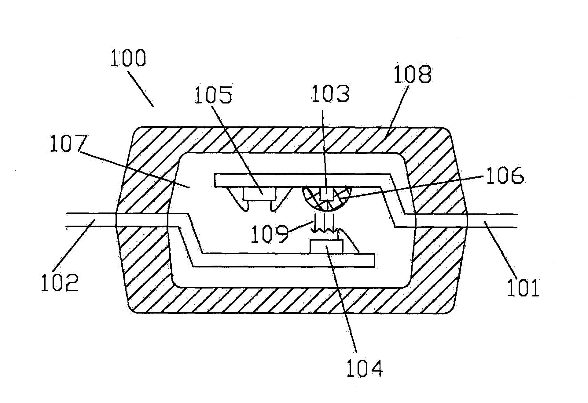
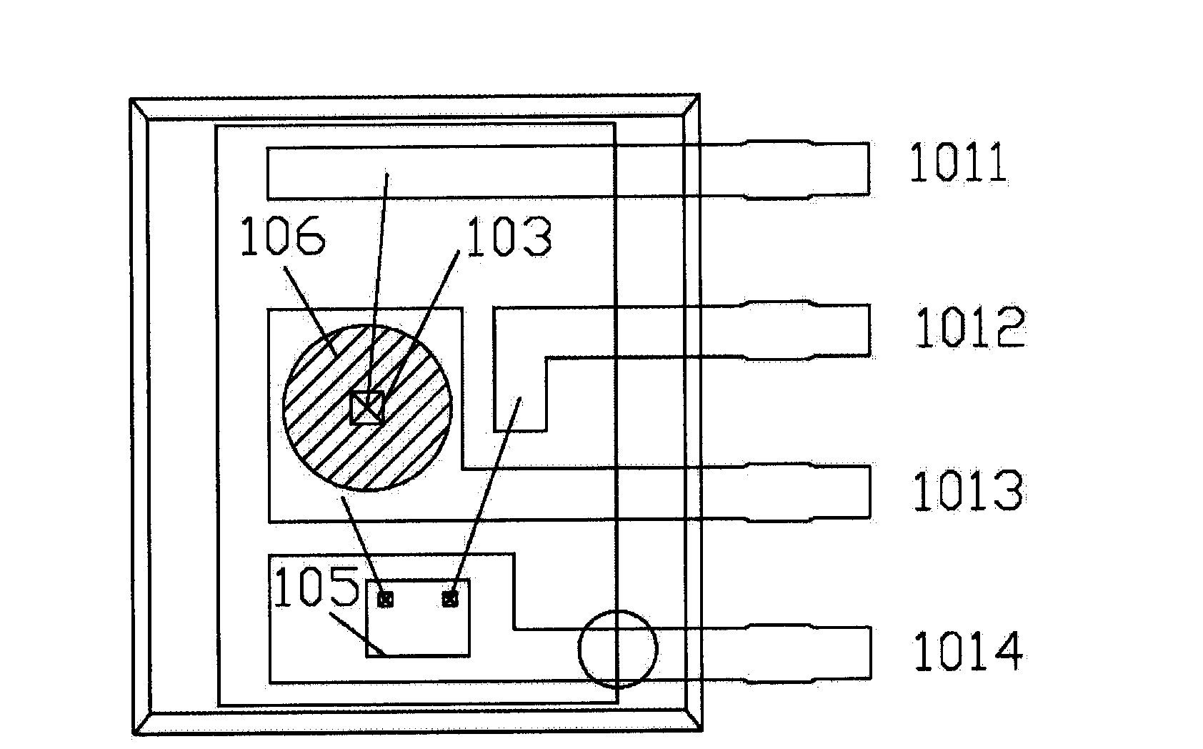
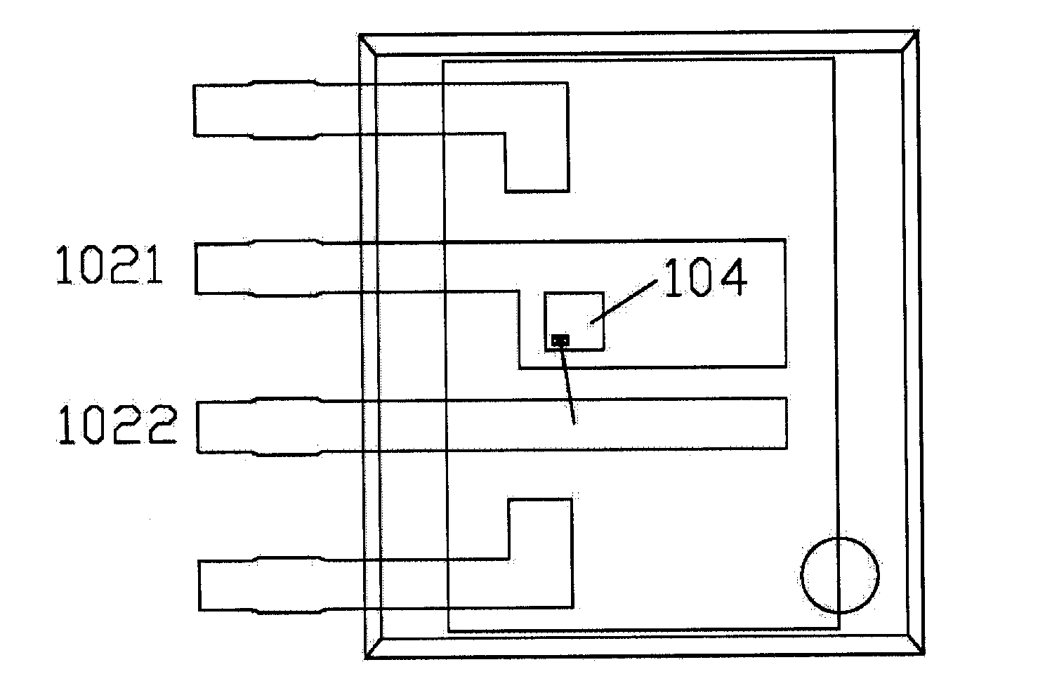
[0019] See figure 1 As shown, it is a schematic cross-sectional view of an optical coupler 100 according to an embodiment of the present invention, wherein the optical coupler 100 mainly includes a first bracket 101, a second bracket 102, a light emitting chip 103, a photosensitive chip 104, an adjustable The voltage stabilizing chip 105 and the multi-layer package covering the first bracket 101 , the second bracket 102 , the light emitting chip 103 , the photosensitive chip 104 , and the adjustable voltage stabilizing chip 105 . The first bracket 101 is arranged opposite to the second bracket 102. The photosensitive chip 104 is arranged on the second bracket 102 to face the light-emitting chip 103. The light-emitting chip 103 is used to emit a light 109, and the photosensitive chip 104 directly receives light from the light-emitting chip. Emitted rays 109 . In this embodiment, the light emitting chip 103 and the adjustable voltage stabilizing chip 105 are jointly disposed on...


PUM


Abstract

The invention provides an optical coupler which comprises a first support, a second support, a luminous chip, a sensitive chip, an adjustable voltage stabilization chip and a multilayer packaging body. The first support is arranged opposite to the second support. The luminous chip is arranged on the first support and emits light. The sensitive chip is arranged on the second support and faces the luminous chip. The multilayer packaging body comprises a first light-transmitting packaging adhesive, a second light-transmitting packaging adhesive and a third lightproof packaging adhesive. The first light-transmitting packaging adhesive covers the luminous chip. The second light-transmitting packaging adhesive covers the sensitive chip and the first light-transmitting packaging adhesive. The third lightproof packaging adhesive covers the second light-transmitting packaging adhesive. The adjustable voltage stabilization chip is arranged on the first support and is electrically connected with the luminous chip. The second light-transmitting packaging adhesive covers the adjustable voltage stabilization chip. By using the optical coupler, a high pressure failure problem caused by colloid delamination is overcome; an adjustable voltage stabilizer does not need to be added; an assembly process is simple and overall occupancy space is small.

Description

technical field [0001] The invention relates to an optical coupler. Background technique [0002] An optocoupler is a safety circuit component that uses light as a medium to transmit electrical signals, and has a good isolation effect on input and output electrical signals. The existing optical coupler generally mainly includes a light-emitting chip and a photosensitive chip, which are respectively arranged on the first bracket and the second bracket. The first bracket and the second bracket are on the same horizontal plane, and the light emitting chip and the photosensitive chip are arranged facing the same direction. The light-emitting chip, the photosensitive chip, and the first bracket and the second bracket that respectively support the light-emitting chip and the photosensitive chip are covered with a layer of light-transmitting colloid, and the outer layer of the light-transmitting colloid is coated with a A light-tight package body is layered, and the surface of th...

Claims


Application Information

Patent Timeline
IPC IPC(8): G02B6/42
Inventor 苏炤亘
Owner EVERLIGHT ELECTRONICS (CHINA) CO LTD
Why Eureka
Try Eureka