
Escapement mechanism, in particular for a clockwork

A technology of escapement and movement, applied in escapement, frequency-stabilizing mechanism, frequency-stabilizing mechanism, etc., can solve problems such as cumbersomeness

Inactive Publication Date: 2012-10-17
CARTIER CRATION STUDIO SA
View PDF10 Cites 3 Cited by
  • Summary
  • Abstract
  • Description
  • Claims
  • Application Information

AI Technical Summary

Problems solved by technology

These mechanisms are also extremely bulky as they require gears that cannot be integrated into the space typically occupied by a conventional escapement, the pallet-escape wheel.

Method used


Image

  • Escapement mechanism, in particular for a clockwork
  • Escapement mechanism, in particular for a clockwork
  • Escapement mechanism, in particular for a clockwork

Examples


Embodiment Construction

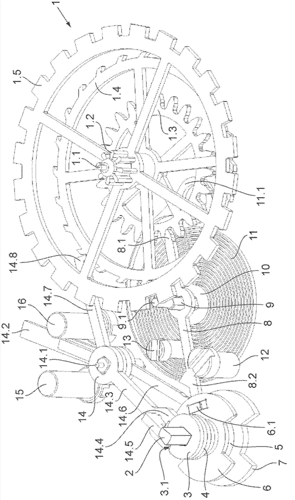
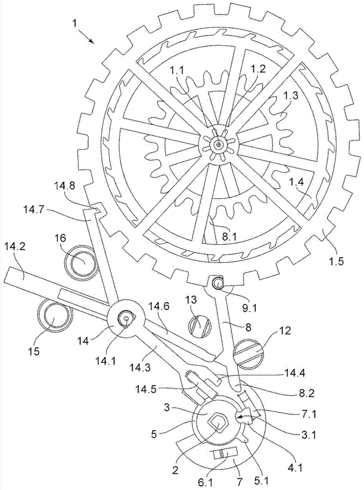
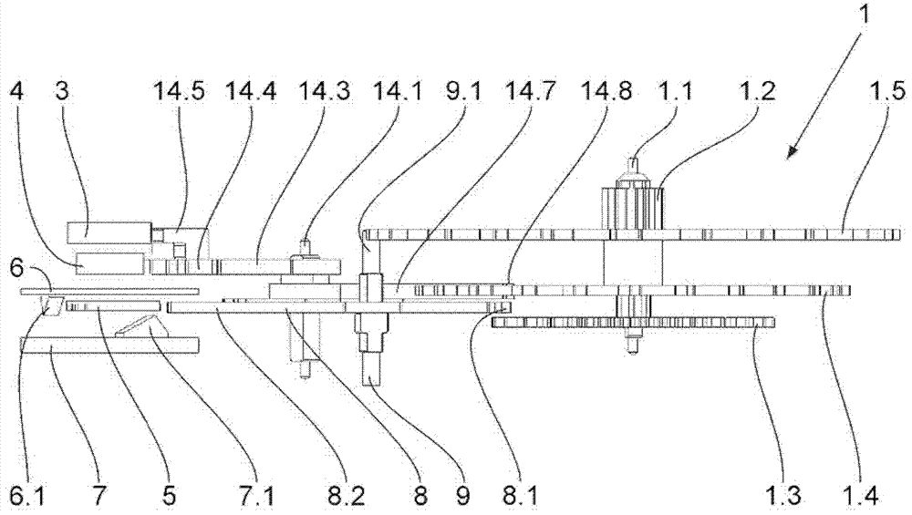
[0018] The accompanying drawings illustrate a constant-force escapement according to the invention, comprising a constant-force auxiliary spring and intended to be equipped in a timepiece movement in which there is a spring balance and by The running wheel train is connected to the escapement transmission of the barrel. Said constant-force escapement is characterized in that it comprises a striking lever pivotally mounted on a part of the frame of the movement, which on the one hand cooperates with the escapement transmission and on the other hand is fixed to the mainspring arbor and in that said constant force auxiliary spring is fixed at one end thereof to a part of the frame of the movement and at the other end to the shaft of the striking rod.

[0019] In the embodiment explained by way of example, the constant-force escapement has an escapement transmission 1 comprising an escapement pinion 1.2 mounted on a shaft 1.1, the escapement pinion passing through a running train ...


PUM


Abstract

The constant force escapement mechanism in particular for a timepiece movement including a spring balance and an escapement gear connected to a barrel by a going train includes a constant force auxiliary spring (11). It includes an impulsion lever (8) co-operating on the one hand with the escapement gear (1) and on the other hand with control members fixed to the arbor of the spring balance. The constant force auxiliary spring (11) is fixed at one of its ends on a part of the frame of the movement and at its other end to the impulsion lever (8).

Description

field of invention [0001] The present invention relates to escapements for timepiece movements, in particular and more particularly to a constant force escapement. Background technique [0002] The purpose of the escapement mechanism used in a watch movement is to ensure the winding of the movement by providing the same energy to the spring hairspring regardless of the winding state of the watch movement barrel. The swing of the hairspring is maintained. [0003] Such constant force escapements are known and typically comprise an auxiliary spring inserted into a kinematic chain connecting the barrel of the movement to the escape wheel of the movement. For example, in document CH120028, the auxiliary spring is recharged only every fifth balance, so that the torque transmitted to the hairspring is not strictly constant for each stroke, since the auxiliary spring is Release between first impact and fifth impact. [0004] Attempts have been made to overcome this disadvantage ...

Claims


Application Information

Patent Timeline
Patent Type & Authority Applications(China)
IPC IPC(8): G04B15/10
CPCG04B15/08G04B15/10G04B17/26G04B15/06
Inventor K·巴斯C·沙泰尔
Owner CARTIER CRATION STUDIO SA
Learn More