
Instrument

A technology for instruments and instrument housings, applied in the direction of instruments, instrument parts, indicating elements, etc., can solve the problems of high cost, complicated control, difficult to drive, etc., and achieve the effect of low cost and unique structural design

Inactive Publication Date: 2012-10-17
HUIZHOU DESAY SV AUTOMOTIVE
View PDF3 Cites 8 Cited by
  • Summary
  • Abstract
  • Description
  • Claims
  • Application Information

AI Technical Summary

Problems solved by technology

[0003] In the prior art, the dials of traditional instruments generally require uniform display of the brightness of the entire dial after the backlight is turned on. Some instruments adopt gradual brightness display in order to create a three-dimensional effect (such as a halo effect). These two methods After the backlight is turned on, the display effect is constant and static. When the instrument pointer points to a certain reading on the dial, the reading is not highlighted, so that the driver sees that all the numbers have the same brightness, which is difficult and easy. To attract the driver's attention, it is inconvenient for the driver to read the information on the dial instantaneously
[0004] In addition, configuring the human-machine interface (HMI) through the virtual instrument (TFT instrument) realizes that when the instrument pointer points to a certain reading on the dial, the reading can be highlighted and highlighted, so that the driver can see the left and right backlight of the reading area The brightness is higher than other areas, and the closer to the pointer, the higher the brightness. Although the effect is realistic and the picture is delicate, it is easy to attract the driver's attention, and it is convenient for the driver to read the information on the dial instantly, but the system control of the virtual instrument scheme is more complicated and higher cost

Method used


Image

  • Instrument
  • Instrument
  • Instrument

Examples


Embodiment Construction

[0019] In order to facilitate the understanding of those skilled in the art, the present invention will be further described in detail below with reference to the drawings and embodiments.

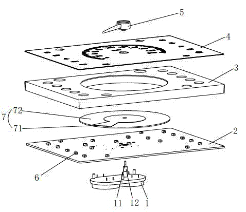
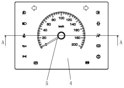
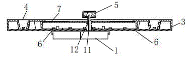
[0020] as attached Figure 1-5 As shown, an instrument includes a driving mechanism 1, a PCB board 2, a backlight bracket 3, a dial 4 and a pointer 5 which are sequentially arranged in the meter housing, the driving mechanism 1 is fixed on the PCB board 2, and the dial 4 is provided with There are numerical values ​​and indication alarm icons, such as numerical values ​​such as vehicle speed, rotational speed, fuel oil or water temperature, indication alarm icons such as high and low beams, seat belts or brakes, etc. The dial 4 is installed on the backlight bracket 3, and the numerical values ​​and indications are on the backlight bracket 3 A light-transmitting hole is provided at the corresponding place of the alarm icon; an LED light 6 is installed on the PCB 2, and the light of the LED ...


PUM


Abstract

The invention relates to an instrument, which comprises a driving mechanism, a printed circuit board (PCB), a backlight support, a graduated disc and a pointer. The driving mechanism, the PCB, the backlight support, the graduated disc and the pointer are sequentially arranged in a shell of the instrument; the driving mechanism is fixed on the PCB; the graduated disc is provided with numerical value and indication alarming icons; the PCB is provided with a light emitting diode (LED) lamp which is used for providing a backlight light source for the graduated disc; the lower part of the pointer penetrates through the graduated disc and the backlight support to be connected with the driving mechanism; a light blocking disc which is also connected with the driving mechanism is arranged at the inner bottom of the backlight support, is made of a light transmitting material, and is provided with a high light transmitting region and a low light transmitting region; and the high light transmitting region is positioned below the pointer. The instrument is unique and novel in structural design and low in cost, when the driving mechanism drives the pointer to rotate, the light blocking disc is driven to synchronously rotate in the same direction, when the pointer of the instrument points to a certain reading on the graduated disc, the reading can be displayed in a highlighting manner, and accordingly a driver can visually know that brightness of left and right parts of the region of the reading is higher than the brightness of other regions, is attracted easily, and can instantly read information on the graduated disc.

Description

technical field [0001] The invention relates to a meter. Background technique [0002] Meters are widely used in vehicles such as automobiles, ships or trains. The pointer of the meter is installed on the motor shaft. The motor drives the pointer of the meter to rotate on the dial through the motor shaft, so that people can read the speed, speed, fuel oil on the dial. or water temperature. [0003] In the prior art, the dials of traditional instruments generally require uniform display of the brightness of the entire dial after the backlight is turned on. Some instruments adopt gradual brightness display in order to create a three-dimensional effect (such as a halo effect). These two methods After the backlight is turned on, the display effect is constant and static. When the instrument pointer points to a certain reading on the dial, the reading is not highlighted, so that the driver sees that all the numbers have the same brightness, which is difficult and easy. To attra...

Claims


Application Information

Patent Timeline
IPC IPC(8): G12B11/00
Inventor 王昭龙刘伟鑫黄亚杰
Owner HUIZHOU DESAY SV AUTOMOTIVE
Learn More