Composite drive type switch reluctance motor with chute structure

A switched reluctance motor, driving technology, applied in the direction of magnetic circuit shape/style/structure, electrical components, electromechanical devices, etc., can solve the problems of low work efficiency, easy to produce fatigue, and labor-intensive users, and achieve work efficiency. Efficient effect

Inactive Publication Date: 2012-10-17
HEBEI UNIV OF ENG
View PDF5 Cites 3 Cited by
  • Summary
  • Abstract
  • Description
  • Claims
  • Application Information

AI Technical Summary

Problems solved by technology

[0002] At present, the motors used in commercially available electric tools are ordinary rotary motors. Electric tools using this type of m

Method used


Image

  • Composite drive type switch reluctance motor with chute structure
  • Composite drive type switch reluctance motor with chute structure

Examples


Embodiment Construction

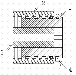
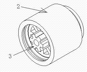
[0010] As shown in the figure, the composite drive switched reluctance motor with a chute structure includes a stator 1, an outer linear drive rotor 2 and an inner rotary drive rotor 3. The stator 1 is made of laminated silicon steel sheets, and there is an excitation magnet on the stator 1. The coil 4 has an external thread on the outer peripheral surface of the stator 1, and an internal thread on the inner wall of the outer linear drive rotor 2 that matches the external thread on the outer peripheral surface of the stator 1. Under the action of electromagnetic force, the outer linear drive rotor 2 is on the stator. 1 rotates axially while rotating, and the internal rotation drives the rotor 3 to be a rotor with a chute structure, and the internal rotation drives the rotor 3 to rotate under the action of tangential electromagnetic force.


PUM


Abstract

The invention discloses a composite drive type switch reluctance motor with a chute structure. The composite drive type switch reluctance motor with the chute structure comprises a stator (1), an external linear driving rotor (2) and an internal rotational driving rotor (3), wherein the stator (1) is formed by laminating silicon steel sheets; an exciting coil (4) is arranged on the stator (1); an external thread is formed on the external circumferential surface of the stator (1); an internal thread matched with the external thread on the external circumferential surface of the stator (1) is formed on the internal wall of the external linear driving rotor (2); under the action of electromagnetic force, the external linear driving rotor (2) moves axially while rotating on the stator (1); and the internal rotational driving rotor (3) has a chute structure and rotate under the action of tangential electromagnetic force. Compared with the prior art, the invention has the advantages that axial feeding force can be automatically generated, so that the labor of a user in work is saved, the user does not feel fatigue in long-term work, and high working efficiency is achieved.

Description

technical field [0001] The invention relates to a motor, in particular to a compound-driven switched reluctance motor with a chute structure used for electric tools for screw tightening, grinding machine processing and spiral lifting table curtains. Background technique [0002] At present, the motors used in commercially available electric tools are ordinary rotary motors. Electric tools using this type of motor do not generate axial feed force, and the user is laborious when working. Long-term labor is prone to fatigue and low work efficiency. . Therefore, designing a compound-driven switched reluctance motor with a chute structure that can automatically generate axial feed force is a technical problem that needs to be solved at present. Contents of the invention [0003] The technical problem to be solved by the present invention is to provide a compound driven switched reluctance motor with a chute structure capable of automatically generating axial feed force. [0...

Claims


Application Information

Patent Timeline
IPC IPC(8): H02K16/02H02K1/12H02K1/24
Inventor 张海军张京军高瑞贞马希青
Owner HEBEI UNIV OF ENG
Why Eureka
Try Eureka