Optical field imaging device and method

A technology of light field imaging and light field image, applied in installation, optics, optical components and other directions, can solve the problem of not being able to obtain high spatial resolution and high directional resolution at the same time, and achieve the effect of convenience and low cost

Active Publication Date: 2012-10-17
SHENZHEN KECHUANG DIGITAL DISPLAY TECH
View PDF4 Cites 77 Cited by
  • Summary
  • Abstract
  • Description
  • Claims
  • Application Information

AI Technical Summary

Problems solved by technology

[0008] Aiming at the bottleneck problem that the current light field imaging technology cannot obtain high spatial resolution and high directional resolution at the same time, the present invention proposes a light field imaging device and method with both high spatial resolution and high directional resolution

Method used


Image

  • Optical field imaging device and method
  • Optical field imaging device and method
  • Optical field imaging device and method

Examples


Embodiment Construction

[0034] The present invention will be further described below in conjunction with the accompanying drawings and embodiments.

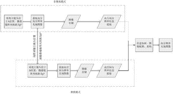
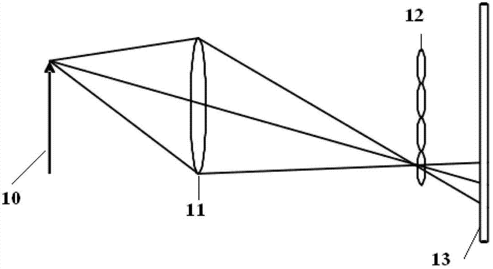
[0035] Figure 4It is a structural schematic diagram of the optical part of the light field imaging device in this embodiment of the present invention; Figure 5 It is a schematic diagram of the workflow of the light field imaging device in this embodiment of the present invention. like Figure 4 , 5 As shown, the light field imaging device provided by this embodiment includes: a main lens 41 whose position can be translated; a variable focus microlens array 42 whose focal length is controllable; a sensor 43 that receives and senses images; 40 in the figure is the main lens object Plane, 44 is the main lens image plane; Make the image plane 44 of the main lens coincide with the position of the variable focus microlens array 42 by correspondingly shifting the main lens, and now the focal length of the variable focus microlens array is the initial foca...


PUM


Abstract

The invention provides an optical field imaging device and method. A device corresponding to the optical filed imaging method enables an image plane of a main lens to be overlapped with the a variable-zoom micro lens array through horizontally moving the main lens; the focal length of the variable-zoom micro lens array is an initial focal length, and the distance between a sensor and the variable-zoom micro lens array is equal to the initial focal length; a first image is obtained by the sensor and the main lens is horizontally moved to enable the image plane to be deviated from the position of the variable-zoom micro lens array; the focal length of the variable-zoom micro lens array is correspondingly adjusted to a second focal length so that the image plane of the main lens is conjugated and imaged on the sensor through the variable-zoom micro lens array to obtain a second image; in the process, the change of the horizontal movement position of the main lens and the focal length of the variable-zoom micro lens array abides by a Gaussian optical law; high-direction resolution rate information of the first image and high-direction resolution rate information of the second image are extracted through an extracting part; and an image processing part is used for carrying out weighting recombination on the extracted information and carrying out registration and reconfiguration on the image to obtain the best imaging effect.

Description

technical field [0001] A light field imaging device and method with high resolution, in particular to a light field imaging device and method with both high spatial resolution and high direction resolution. Background technique [0002] The imaging process of traditional cameras adopts a two-dimensional projection method for three-dimensional space scenes, and only accumulates the intensity of light on the detector pixels, that is to say, only the spatial distribution of objects on the image plane is considered, and the The propagation direction information of the light is discarded, and the reshaping of the image is limited. Light field imaging retains the possibility of image reshaping, can obtain more flexible and diversified image information, and has a very broad application prospect. For example, the digital refocusing technology of light field pictures can be used to calculate the two-dimensional images focused at different depths, so as to realize the function of "t...

Claims


Application Information

Patent Timeline
Patent Type & Authority Applications(China)
IPC IPC(8): H04N5/225H04N5/232H04N13/02G02B27/00G02B7/04
Inventor 张薇庄松林杨波
Owner SHENZHEN KECHUANG DIGITAL DISPLAY TECH
Why Eureka
Try Eureka