
Sound-actuated illumination circuit

A circuit, monostable circuit technology, applied in the field of acoustically actuated lighting circuits, can solve the problem that the circuit cannot change the response easily, and achieve the effects of improved consistency and selection range, rapid process and high cost efficiency

Inactive Publication Date: 2012-10-17
BENMORE VENTURES LTD
View PDF9 Cites 1 Cited by
  • Summary
  • Abstract
  • Description
  • Claims
  • Application Information

AI Technical Summary

Problems solved by technology

For stationary equipment, this is not a problem, but for moving arrangements of items, existing circuits cannot easily change their response when the environment changes from very noisy to relatively quiet (or vice versa)

Method used


Image

  • Sound-actuated illumination circuit
  • Sound-actuated illumination circuit
  • Sound-actuated illumination circuit

Examples


Embodiment Construction

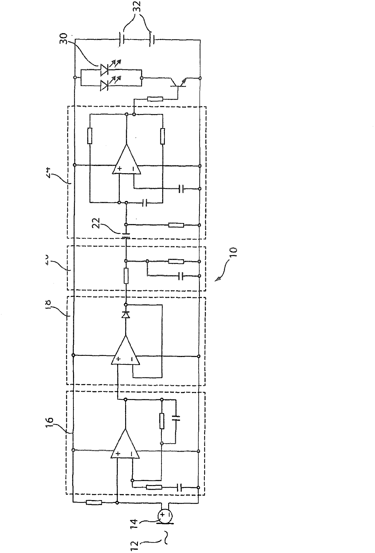
[0041] With reference to the accompanying drawings, figure 1 A circuit 10 is shown for flashing a light source in the form of an LED 30 in time with an input acoustic signal 12 . An input acoustic signal 12 , in particular a music signal, is detected by an electret condenser microphone 14 . It is supplied to a band pass amplifier 16 which amplifies signals in the range 50 Hz to 160 Hz.

[0042] The output of the bandpass amplifier is connected to the input of a peak detector circuit 18 configured to respond to rising edges of the input signal. The output peak value of the peak detector is proportional to the peak level of the loudest audio sound within the specified audio frequency band.

[0043] The output of the peak detector circuit 18 is connected to a filter circuit 20 . It is used to remove noise disturbances and other unwanted high and low frequency signals to keep the peaks as clean as possible. A musical beat that is distinct and distinct from other sounds in the ...


PUM


Abstract

A circuit (10), for causing a light source (30) to flash in correspondence to the peak amplitudes of an incoming sound signal, e.g. music (12), comprises an audio transducer (14), a band-pass amplifier (16), a peak detector section (18), and a filter (20) connected to a monostable circuit (24) via a capacitor (22). The light source (30) comprises one or more surface mount LED devices, and can be used to illuminate the contents of a container, e.g. a drinks bottle.

Description

Background technique [0001] Circuits for actuating strobe lights in time with music in nightclubs are well known. Such circuits are part of relatively large sets of stationary equipment. WO2004 / 110892 discloses a light source connected to a container, such as a beverage bottle, and arranged to be activated by sound waves from a loudspeaker in a nightclub. Certain sound waves, such as the bass output, are programmed to act as triggers for the light source to flash in time with the music. [0002] Existing circuits are characterized in that they are only capable of responding to a relatively narrow range of sound levels, typically the 15 dB range. For stationary devices, this is not a problem, but for moving arrangements, existing circuits cannot easily change their response when the environment changes from very noisy to relatively quiet (and vice versa). Contents of the invention [0003] Aspects of the present invention seek to overcome, or at least alleviate, the above-...

Claims


Application Information

Patent Timeline
IPC IPC(8): H05B37/02H05B33/08H05B44/00
CPCH05B33/0854H05B37/0236H05B45/10H05B47/12Y02B20/40
Inventor 布林·格里菲思乔恩·邓肯
Owner BENMORE VENTURES LTD
Learn More