
Molecular distillation device

A molecular distillation and equipment technology, applied in the field of molecular distillation equipment, can solve the problems of high operation and maintenance costs, difficult vacuum sealing, complex structure, etc., and achieve low equipment manufacturing and operation and maintenance costs, saving power resources, and high thermal energy utilization. Effect

Active Publication Date: 2012-10-24
饶攀
View PDF5 Cites 13 Cited by
  • Summary
  • Abstract
  • Description
  • Claims
  • Application Information

AI Technical Summary

Problems solved by technology

2. Ordinary distillation has bubbling and boiling phenomena, while molecular distillation is free evaporation on the surface of the liquid film, and the operating pressure is very low. Generally, it is on the order of 0.1-1Pa, and the heating time is very short, generally only ten seconds to several minutes.
3. Evaporation and condensation in ordinary distillation are reversible processes, and there is a dynamic phase equilibrium between the liquid phase and the gas phase, while in the molecular distillation process, the molecules escaping from the heating surface fly directly to the condensation surface, and theoretically do not return to the heating surface Possibility, so molecular distillation has no hard-to-separate substances
[0003] Although the evaporation efficiency of molecular distillation equipment is high, the structure is complicated, the vacuum sealing is difficult, the manufacturing cost of the equipment is expensive, and the cost of operation and maintenance is also very high

Method used


Image

  • Molecular distillation device
  • Molecular distillation device
  • Molecular distillation device

Examples


Embodiment 1

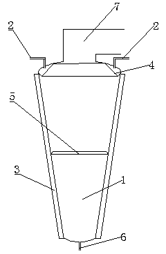
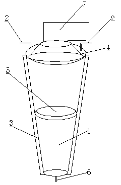
[0021] Embodiment 1: It includes a molecular distillation equipment body 1 and a vacuum tube 7. The molecular distillation equipment body 1 is an inverted body circular platform with an upper ring larger than the lower ring, and the two generatrices opposite to the inverted body annular platform intersect The formed angle is 45°-85°. Preferably: the cone angle of the inverted circular truncated cone is 60°-70°. The circular frustum is hollow, and the wall thickness of the frustum is uniform. The same is true for the circular frustum involved in the following embodiments. The two opposite generatrices refer to the two waists of a trapezoid obtained by vertically cutting the circular platform with a plane along the center of the circular platform. The same is true for the relative busbars referred to in the following embodiments.

[0022] The top of the molecular distillation equipment body 1 is connected to the top head, the top head is connected to the material feeding pipe...

Embodiment 2

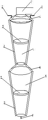
[0027] When the product output is small, one molecular distillation equipment body can be used as the molecular distillation equipment body; when the product output is large, two or more molecular distillation equipment bodies can be welded into a large molecular distillation equipment. Such as image 3 As shown: the upper and lower molecular distillation equipment bodies 1 and 8 are connected in series, and the bottom port of the upper molecular distillation equipment body 1 is connected to the top port provided on the top head of the lower molecular distillation equipment body 8 .

[0028] The top end of the upper molecular distillation equipment body 1 is provided with a top port to connect with the vacuum tube 7. The inlet of the vacuum tube 7 is located in the upper circular ring of the upper distribution circular platform composed of the material distribution tank plate 4. The upper molecular distillation equipment body The top head of 1 is connected to the material feed...

Embodiment 3

[0030]Embodiment 3: A condensing system 9 is provided in the inner cavity of the molecular distillation equipment body 1, the top head of the molecular distillation equipment body 1 is connected to the material feeding pipe 2, and the inner wall of the top head head of the molecular distillation equipment body 1 is connected to the inner wall of the molecular distillation equipment body 1 by There is an annular gap between the lower end of the distribution ring-shaped circular platform composed of the material distribution channel plate 4 and the side wall of the molecular distillation equipment body 1, and the outlet of the material feeding pipe 2 is in the material distribution In the material distribution tank formed by the tank plate 4 and the inner wall of the molecular distillation equipment body 1, the middle part of the side wall of the molecular distillation equipment body 1 is connected to the lower end of the ring-shaped circular platform composed of the material redi...


PUM


Abstract

The invention discloses a molecular distillation device which comprises a molecular distillation device body (1) and a vacuum pipe (7) and is characterized in that the molecular distillation device body (1) is an inversion body annular round table with the upper ring larger than the lower ring. The included angle formed by intersection of two opposite generatrixes of the inversion body annular round table ranges from 45 degrees to 85 degrees. The body is connected with a top end sealing head connected with a material adding pipe (2), and the inner wall of the top end sealing head is connected with the upper end side of a distribution annular round table formed by material distribution groove plates (4). An annular gap is retained between the lower end side of the distribution annular round table formed by the material distribution groove plates (4) and the lateral wall of the body, and an outlet of the material adding pipe (2) is arranged in a distribution groove. The middle of the lateral wall of the body is connected with the lower end side of a redistribution annular round table formed by material redistribution groove plates (5). An upper body and a lower body of the device body are connected in series when necessary, and a condensation system is arranged in an inner cavity of the body. The molecular distillation device is good in sealing effect, and a film is automatically formed from top to bottom along the table face by materials. The molecular distillation device does not require stirring and has the advantages of saving electricity, improving heat energy utilization ratio, reducing production cost and the like.

Description

technical field [0001] The invention belongs to the technical field of mechanical equipment, and relates to distillation and purification equipment for oil and chemical products, in particular to molecular distillation equipment. Background technique [0002] Molecular distillation, also known as short-path distillation, is a relatively new liquid-liquid separation technology that has not been widely used in industrial production. Its application can solve a large number of problems that cannot be solved by conventional distillation technology. Compared with conventional distillation technology, it has the following advantages: 1. Ordinary distillation operates at the boiling point, while molecular distillation can be separated at any temperature as long as there is a sufficient temperature difference between the hot and cold surfaces. Therefore, the operating temperature of molecular distillation is much lower than the boiling point of the material. 2. Ordinary distillat...

Claims


Application Information

Patent Timeline
IPC IPC(8): B01D3/12
Inventor 饶攀
Owner 饶攀
Learn More