Workpiece guide device of steel plate blanking unit

A technology for guiding devices and workpieces, applied in the direction of feeding devices, positioning devices, storage devices, etc., can solve problems such as low work efficiency, affecting feeding, production accidents, etc., to save manpower, reduce shoveling force, and improve work efficiency. efficiency effect

Inactive Publication Date: 2015-04-15
重庆宝钢汽车钢材部件有限公司
View PDF9 Cites 0 Cited by
  • Summary
  • Abstract
  • Description
  • Claims
  • Application Information

AI Technical Summary

Problems solved by technology

[0003] Since the steel plate automatic cutting line is a continuous production line, it needs to continuously transport the steel plate. During the conveying process, the steel plate needs a high conveying accuracy to ensure that the steel plate enters the cutting and blanking process correctly. This process generally adopts rail transportation. In addition to the transportation function, the rail also has It has a guiding function to ensure that the steel plate is conveyed in a predetermined straight line. If the steel plate is deflected during the conveying process, it will affect the normal progress of subsequent production and even cause production accidents; especially when the front end of the steel plate is transported into the track, due to There is a large scraping force with the track, which will even affect the feeding, while the existing process is manually lifted to ensure the smooth progress of production, which wastes manpower and lower work efficiency

Method used


Image

  • Workpiece guide device of steel plate blanking unit
  • Workpiece guide device of steel plate blanking unit
  • Workpiece guide device of steel plate blanking unit

Examples


Embodiment Construction

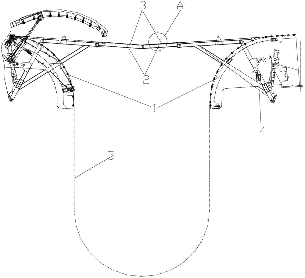
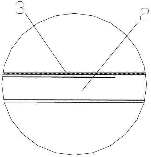
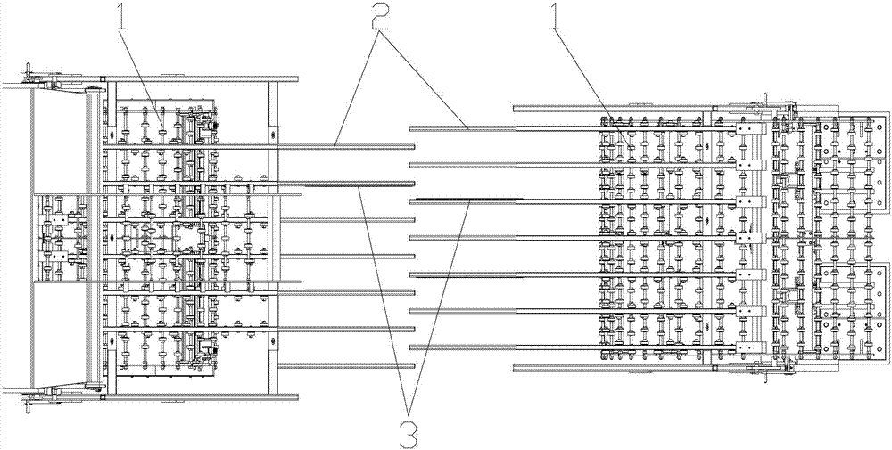
[0021] figure 1 It is a schematic diagram of the structure of the present invention, figure 2 for figure 1 Enlarged view at A, image 3 It is a top view of the present invention, as shown in the figure: the workpiece guiding device of the steel plate blanking unit of this embodiment includes two curved rails 1 that are convex and downward, and the two curved rails 1 are arranged opposite to each other and transported on the workpiece 5. Directly connect the linear rails for conveying workpieces, that is, they are arranged symmetrically in the longitudinal direction; a distance is formed between the two arc-shaped rails 1 to make the workpiece 5 droop in a U-shape; as shown in the figure, the arc-shaped rails 1 are arranged oppositely, and the (Workpiece 5) When passing through the arc-shaped track, through mechanical control, the gravity of workpiece 5 can be used to form a U-shaped drooping structure. This structure has an automatic deviation correction function when the s...


PUM


Abstract

The invention discloses a workpiece guide device of a steel plate blanking unit, which comprises two arc rails which are convex outward and are bent downward and a guiding assembly for guiding to load a workpiece. The guiding assembly consists of guiding frames and a driving device; and at least one longitudinal rod of the guiding frames is provided with a longitudinal bulge protruding out of the upper surface of the corresponding guiding frame. According to the invention, a structure of the opposite arc guide rails is adopted and a certain distance is set; when a steel plate is conveyed, the steel plate is sunk into a U shape between the two arc guide rails by utilizing the gravity of the steel plate and the U-shaped steel plate is automatically regulated by utilizing the gravity of the steel plate to ensure that the longitudinal center line of the steel plate is consistent with the conveying direction; the workpiece guide device has an automatic correcting function, so that a conveying deflection angle is prevented and the steel plate is ensured to be conveyed according to the set straight line; meanwhile, by utilizing the guiding frames which can swing upward and downward, the contact areas between the guiding frames and the front end and the integral lower surface of the steel plate are reduced, so that the friction force and the scraping force are reduced; and most of scraping force is eliminated for the front end of the steel plate in the feeding process, so that the steel plate smoothly enters the subsequent process, the labor is saved and the working efficiency is improved.

Description

technical field [0001] The invention relates to an accessory device of a steel plate blanking unit, in particular to a workpiece guiding device of a steel plate blanking unit. Background technique [0002] As a processing raw material, steel plate needs to be cut in the early stage. With the development of science and technology, steel plate cutting has developed from the original manual cutting to automatic cutting, with high work efficiency. [0003] Since the steel plate automatic cutting line is a continuous production line, it needs to continuously transport the steel plate. During the conveying process, the steel plate needs a high conveying accuracy to ensure that the steel plate enters the cutting and blanking process correctly. This process generally adopts rail transportation. In addition to the transportation function, the rail also has It has a guiding function to ensure that the steel plate is conveyed in a predetermined straight line. If the steel plate is def...

Claims


Application Information

Patent Timeline
Patent Type & Authority Patents(China)
IPC IPC(8): B21D43/02
Inventor 张本华范伟陈懋剑黎泰丞
Owner 重庆宝钢汽车钢材部件有限公司
Why Eureka
Try Eureka