Shaft core processing mold

A technology for processing molds and shaft cores. It is applied in the direction of manufacturing tools, metal processing equipment, and cores. It can solve the problems of increasing production costs, not being on the same line, wasting manpower and material resources, etc., and improving the yield and concentricity. Good, the effect of reducing waste

Inactive Publication Date: 2012-10-24
KUNSHAN SHENCHANG PRECISION METAL PROD
View PDF7 Cites 0 Cited by
  • Summary
  • Abstract
  • Description
  • Claims
  • Application Information

AI Technical Summary

Problems solved by technology

The shaft core of the existing production clutch output shaft uses a sleeve and two mold cores. The concentricity and precision are poor during installation, resulting in that the center line of the shaft core and the shaft rod are not on the same straight line after casting, resulting in a lot of waste. manpower and material resources, increasing the production cost of the enterprise

Method used


Image

  • Shaft core processing mold
  • Shaft core processing mold

Examples


Embodiment Construction

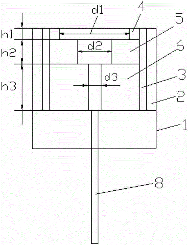
[0015] The present invention will now be further described in detail in conjunction with the accompanying drawings and embodiments. These drawings are all simplified schematic diagrams, only illustrating the basic structure of the present invention in a schematic manner, so it only shows the composition related to the present invention.

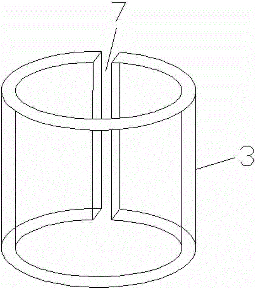
[0016] Such as figure 1 , figure 2 As shown, a shaft core processing mold includes a mold base 1, a mold shell 2 is fixed on the mold base 1, and a hollow cylindrical sleeve 3 is arranged inside the mold shell 2, and the sleeve 3 is provided with a The first set 4, the second set 5, and the third set 6 are stacked successively from top to bottom. The outer diameters of the first set 4, the second set 5, and the third set 6 are the same, but the inner diameter and height are different. .

[0017] The peripheral surface of the sleeve 3 has a gap 7 along the axis, so that the sleeve 3 has a certain degree of expansion when it is squeezed,...


PUM


Abstract

The invention relates to a shaft core processing mold, which comprises a mold base; a mold shell is fixed on the mold base; a hollow cylindrical sleeve is arranged in the mold shell; a first sleeve, a second sleeve and a third sleeve are sequentially disposed in the sleeve from top to bottom in an overlapping way; the external diameters of the first sleeve, the second sleeve and the third sleeve are the same, but the inner diameters are different from the heights. The invention is simple in structure, and convenient for use; processed products have good concentricity and high precision, and meet client requirements; the yield is increased; raw material waste is reduced; a mandril is disposed for mutual separation of the mold from the shaft core during mold splitting; and the problem that a product is left in the mold shell and can not be taken out is avoided.

Description

technical field [0001] The invention relates to a mold, in particular to a shaft core processing mold. Background technique [0002] The shaft core is generally installed in the output shaft of the automobile clutch. The clutch is located in the flywheel housing between the engine and the gearbox. The output shaft of the clutch is the input shaft of the gearbox. During the driving process of the car, the driver can step on or release the clutch pedal as needed to temporarily separate and gradually engage the engine and the transmission, so as to cut off or transmit the power input from the engine to the transmission. The shaft core of the existing production clutch output shaft uses a sleeve and two mold cores. The concentricity and precision are poor during installation, resulting in that the center line of the shaft core and the shaft rod are not on the same straight line after casting, resulting in a lot of waste. Human and material resources increase the production ...

Claims


Application Information

Patent Timeline
Patent Type & Authority Applications(China)
IPC IPC(8): B22C9/22
Inventor 陈海霞
Owner KUNSHAN SHENCHANG PRECISION METAL PROD
Why Eureka
Try Eureka