Combined cutter

A technology of combining cutting tools and blades, which is applied in drilling accessories, manufacturing tools, drilling/drilling equipment, etc., can solve the problem of inability to realize reaming, countersinking processing, installation accuracy directly affecting holes, and failure to achieve integrated processing and other problems, to achieve the effect of simple installation, simple structure, and easy replacement operation

Inactive Publication Date: 2012-10-24
YANCHENG DUOWEI GROUP
View PDF10 Cites 1 Cited by
  • Summary
  • Abstract
  • Description
  • Claims
  • Application Information

AI Technical Summary

Problems solved by technology

This kind of tool is mainly used for metal processing, with high efficiency and good surface quality, but it is not suitable for composite materials.
In addition, three kinds of tools are assembled and used, the assembly accuracy is not easy to guarantee and the assembly is difficult, the vibration is large during boring processing, the cutting force is unstable, and large defects will occur when processing carbon fiber composite materials, and this kind of tool does not reach the drilling, countersinking, guiding Corner integration processing requirements
[0006] In the patent inventions for drilling in the past, there are examples of different types of compound cutters, such as a combination cutter disclosed by CN2235347Y, which realizes drilling, boring and twisting of holes by setting additional cutters on the cutter bar One-time processing, but the defect of this tool is that it only trims the hole, the processing amount is small, the installation accuracy of the blade directly affects the accuracy of the hole, and it cannot realize reaming and countersinking, especially when processing The cutting force is large, which may easily lead to the deviation of machining accuracy

Method used


Image

  • Combined cutter
  • Combined cutter

Examples


Embodiment Construction

[0018] The present invention will be described in further detail below in conjunction with the accompanying drawings.

[0019] In the description of the present invention, the terms "upper", "lower", "left", "right", etc. indicate the orientation or positional relationship based on the orientation or positional relationship shown in the drawings, and are only for the convenience of describing the present invention rather than requiring The invention must be constructed and operated in a particular orientation and therefore should not be construed as limiting the invention.

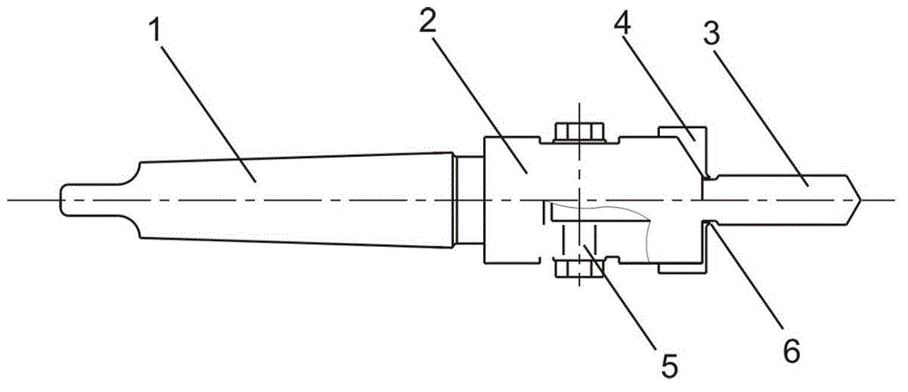
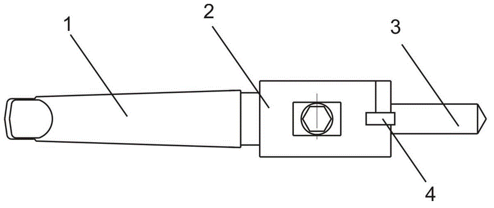
[0020] figure 1 It is the front view of the combined tool of the present invention, such as figure 1 As shown, a combined tool, which is followed by a countersink 1, a clamping part 2, a blade 4 and a drill 3 along the horizontal direction, the blade 4 is clamped by the clamping part 2 and the drill 3 in the vertical direction, and the clamping The holding part 2 completes the clamping of the countersink...


PUM


Abstract

The invention discloses a combined cutter, which comprises a counter bit, a clamping section and a drill bit, and also comprises a blade, wherein the blade is clamped together with the drill bit in the vertical direction through the clamping section, and a lead angle opening is molded on a connected part of the drill bit and the clamping section. According to the invention, once molding and drilling of different types of materials can be achieved; a processing procedure is reduced, and the processing efficiency can be obviously improved.

Description

technical field [0001] The invention belongs to the technical field of machining and manufacturing, and in particular relates to a combined tool integrating countersinking, drilling and chamfering. Background technique [0002] In industrial production, the processing of countersinking is widely used. The traditional processing mode is to first drill the hole with a drilling machine equipped with a drill bit, and then pass through a drilling machine equipped with a countersinking drill. This processing mode requires two equipments, The two processes of drilling and countersinking are performed manually, which is time-consuming and labor-intensive, which increases the processing cost, and it is difficult to completely align and coincide with the center line of rotation of the countersinking and drilling process, and the processing accuracy is greatly reduced. [0003] A countersinking tool provided by the prior art integrates the drill bit and countersinking of the tool. Alth...

Claims


Application Information

Patent Timeline
Patent Type & Authority Applications(China)
IPC IPC(8): B23B51/08
Inventor 高军魏成存束必宏
Owner YANCHENG DUOWEI GROUP
Why Eureka
Try Eureka