Special sponge grinding material spraying device

A kind of abrasive and sponge technology, applied in the field of surface cleaning equipment, can solve the problems of low work efficiency, not easy to fall, poor fluidity, etc., and achieve the effect of simple structure, no blockage of pipelines, and overcoming shed materials

Active Publication Date: 2012-10-24
淄博大亚金属科技股份有限公司
View PDF7 Cites 10 Cited by
  • Summary
  • Abstract
  • Description
  • Claims
  • Application Information

AI Technical Summary

Problems solved by technology

However, in actual use, it is found that since the sponge abrasive itself has been compressed, it has problems such as light weight, large particles, and poor fluidity. Problems such as low efficiency lead to great restrictions on the application of market promotion

Method used


Image

  • Special sponge grinding material spraying device
  • Special sponge grinding material spraying device
  • Special sponge grinding material spraying device

Examples


Embodiment 1

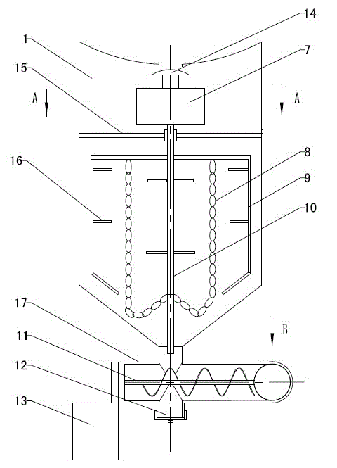
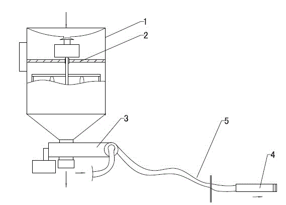
[0027] Refer to attached Figure 1~4 : This kind of sponge abrasive spraying equipment is mainly composed of a material storage pressure tank 1, a stirring device 2, a screw feeding device 3, a nozzle 4 and a compressed air power system 5, and the material storage pressure tank 1 is vertically fixed by a central shaft 10 Install the stirring device 2, the top of the stirring device 2 is provided with an on-off switch 14 that controls the opening and closing of the top feed port of the storage pressure tank 1, and the outlet at the bottom of the storage pressure tank 1 is connected to the feed port of the screw feeding device 3, and the screw feeding device 3 The outlet is connected to the feed hole of the nozzle 4 through a pipeline, and one side of the inlet hole of the nozzle 4 is connected to the compressed air power system 5, and the compressed air is supplied to the nozzle 4 through the pipeline.

[0028] Stirring device 2 is chain type, adopts electric or pneumatic contr...

Embodiment 2

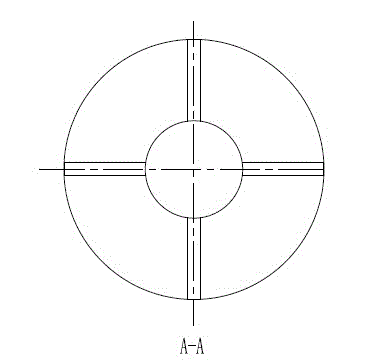
[0037] Refer to attached Figure 5 : Stirring device 2 is a chain type, adopts electric or pneumatic control, and comprises pneumatic stirring motor 7, fixed support 15, stirring support 9 and stirring chain 8 installed on the central shaft 10 successively from top to bottom, and the cross section of fixed support 15 is formed Cross-shaped, the four ends are fixedly connected to the inner wall of the material storage pressure tank 1, the center is connected to the central shaft 10 through bearings, the stirring support 9 is fixedly connected to the central shaft 10, and the stirring support 9 is fixedly connected to the suspended stirring chain 8 .

[0038] The working principle and working process are the same as those in Embodiment 1.

Embodiment 3

[0040] Refer to attached Figure 6 Stirring device 2 includes pneumatic stirring motor 7, fixed support 15, stirring support 9 and stirring teeth 16 installed on the central shaft 10 successively from top to bottom, the cross section of fixed support 15 is cross-shaped, and four ends are fixedly connected to On the inner wall of the material storage pressure tank 1, the center is connected to the central shaft 10 through a bearing, and the stirring support 9 is fixedly connected to the central shaft 10. On the inner wall of the stirring support 9 and on the central shaft 10, a plurality of horizontally arranged stirring teeth 16 are evenly distributed. The stirring teeth 16 on the inner wall of the support 9 and the stirring teeth 16 on the central shaft 10 are arranged at intervals or correspondingly.

[0041] The working principle and working process are the same as those in Embodiment 1.


PUM


Abstract

The invention discloses a special sponge grinding material spraying device, belongs to the field of surface cleaning equipment, and particularly relates to a special sponge grinding material spraying device which comprises a material storage pressure tank (1) and a nozzle (4). The special sponge grinding material spraying device is characterized in that a stirring device (2) is vertically and fixedly mounted in the material storage pressure tank (1) by a center shaft (10), an opening switch (14) used for controlling a feed inlet on the top of the material storage pressure tank (1) is disposed on the top of the stirring device (2), a feed inlet of a spiral feeding device (3) is connected to an outlet at the bottom of the material storage pressure tank (1), a discharge outlet of the spiral feeding device (3) is connected with a material inlet hole of the nozzle (4) by a pipeline, and a compressed air power system (5) is connected to one side of an air inlet hole of the nozzle (4). The special sponge grinding material spraying device has the advantages that the special sponge grinding material spraying device is simple in structure, convenient to use, fine in fluidity and high in efficiency, is not blocked easily, and the like.

Description

technical field [0001] A special spraying equipment for sponge abrasives belongs to the field of surface cleaning equipment, in particular to a special spraying equipment for sponge abrasives. Background technique [0002] In the abrasive cleaning industry, a sponge abrasive made of polyurethane elastomer and rigid abrasive is widely used on the surface because it can absorb dust during the cleaning process and has the advantages of no splashing and no damage to the surrounding working surface. Clean up the industry. However, in actual use, it is found that since the sponge abrasive itself has been compressed, it has problems such as light weight, large particles, and poor fluidity. Problems such as low efficiency lead to great restrictions on the application of market promotion. Contents of the invention [0003] The technical problem to be solved by the present invention is to overcome the deficiencies of the prior art and provide a special spraying equipment for spong...

Claims


Application Information

Patent Timeline
Patent Type & Authority Applications(China)
IPC IPC(8): B24C3/02
Inventor 赵松乔韩庆吉韩超殷凤仕
Owner 淄博大亚金属科技股份有限公司
Why Eureka
Try Eureka