Wire dividing plate of cold cast anchorage and wire dividing method thereof

A technology of cold casting anchors and wire splitters, which is applied to bridge parts, erecting/assembling bridges, bridges, etc., can solve the problems of increasing the amount of cold casting materials and sealing materials, extending sealing sleeves, and high strength of steel wires, so as to improve Effects of injection rate, shortened length, and extended service life

Active Publication Date: 2012-10-24
JULI SLING
View PDF5 Cites 6 Cited by
  • Summary
  • Abstract
  • Description
  • Claims
  • Application Information

AI Technical Summary

Problems solved by technology

[0003] Traditional splitter board such as figure 1 As shown, each steel wire of the steel wire bundle is bent and penetrated into the wire splitting plate before making the anchor head, and the wire splitting efficiency is low; due to the high strength of the steel wire, it is not easy to bend, and it is necessary to strip off a long enough high-density polyethylene (PE) The sheath steel wire can penetrate the wire splitting plate; at the same time, it is necessary to extend the sealing sleeve and increase the amount of cold casting material and sealing material

Method used


Image

  • Wire dividing plate of cold cast anchorage and wire dividing method thereof
  • Wire dividing plate of cold cast anchorage and wire dividing method thereof
  • Wire dividing plate of cold cast anchorage and wire dividing method thereof

Examples


Embodiment Construction

[0021] The preferred embodiments of the present invention will be described below in conjunction with the accompanying drawings. It should be understood that the preferred embodiments described here are only used to illustrate and explain the present invention, and are not intended to limit the present invention.

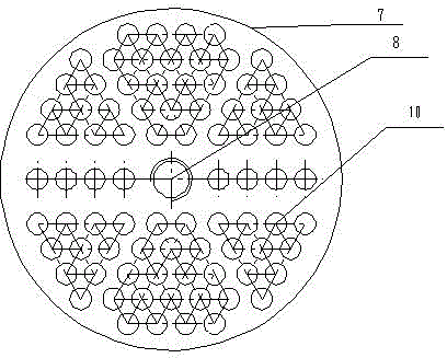
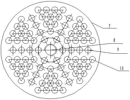
[0022] like figure 2 As shown, the splitter plate of the cold-cast anchor includes the splitter plate 7 as a plane, and the center of the splitter plate 7 is provided with a threaded hole 8, and the periphery of the threaded hole 8 is evenly distributed with six rows of inline holes 9 and six Some of the holes 10 arranged in a regular triangle, the holes arranged in a straight line and the holes arranged in a regular triangle are alternately arranged. According to the arrangement and distribution of the steel wires of the cable body, the number of holes arranged in-line in each row is at least 2, and the number of holes in the in-line arrangement in each row is at ...


PUM


Abstract

The invention provides a wire dividing plate of a cold cast anchorage, which comprises a wire dividing plate main body. The wire dividing plate main body is a plane; a screw hole is arranged at the center of the wire dividing plate; six lines of holes arranged in a straight line and six groups of holes in regular triangle arrangement are evenly distributed along the circumference of the screw hole in a radial manner; and the straight-line holes and the regular triangle hole groups are alternately arranged. The wire dividing method includes the following steps of: bundling semi-parallel steel wires into a regular hexagonal or chamfer hexagonal shape in tight arrangement; in the wire dividing process, inserting an awl along the interlayer of a steel wire bundle, then inserting three rows of thin steel wires with appropriate diameter, wherein the angle between every two rows of thin steel wires is 120degrees; replacing the two thin steel wires at the middle of each row of steel wires with thick steel wires, adjusting the axial positions of the thin and thick steel wires so as to enable the tips of the steel wires to be in arrangement consistent with the holes of the wire dividing plate; buckling the wire dividing plate into the steel wire bundle, jacking the wire dividing plate to an appropriate position through a pipe-jacking for the convenience of upsetting the steel wires, upsetting the steel wires, pulling back the wire dividing plate, and conducting the treatments of sealing, pouring, vibrating and curing. The wire dividing plate has the characteristics of high production efficiency, good anchoring performance and long service life.

Description

technical field [0001] The invention belongs to the field of bridge components, in particular to a wire dividing plate for bridge stay cables. Background technique [0002] Cable-stayed bridges have a long history. In recent decades, along with the development and progress of science and technology, they have been widely promoted. As the stress member bearing the main load of the cable-stayed bridge, the hot-extruded polyethylene high-strength steel wire cable of the cable-stayed bridge is the cable-stayed cable. The development of the cable-stayed cable has promoted the development of the cable-stayed bridge. At present, factory-made stay cables are widely used for their high elastic modulus, good fatigue performance, high tensile strength, good anti-corrosion performance, and easy installation. The wire splitting plate is an important part of the cold cast anchor of the cable stay. The wire splitting plate not only has the function of splitting the wire, but also bears th...

Claims


Application Information

Patent Timeline
Patent Type & Authority Applications(China)
IPC IPC(8): E01D19/14E01D21/00
Inventor 杨建国王瑛崔建英禹洪楷
Owner JULI SLING
Why Eureka
Try Eureka