Cutting device of coal cutter

A shearer, drum technology applied to cutting rods. It can solve the problems that affect the amount of undercover, cannot meet the needs of thin coal seam or thin coal seam mining, low transmission efficiency, etc., and achieve the effect of solving the problem of coal loading

Inactive Publication Date: 2012-10-24
SHANGHAI TIANDI MINING EQUIP TECH CO LTD +1
View PDF1 Cites 2 Cited by
  • Summary
  • Abstract
  • Description
  • Claims
  • Application Information

AI Technical Summary

Problems solved by technology

[0002] Existing drum-type cutting devices of coal shearers widely use motors to be arranged horizontally, and each cutting part is driven by an independent motor. transmission, and then decelerate the drive drum through the planetary gear system to realize its cutting function. With the continuous development of coal mining technology, the power of the shearer cutting device is also increasing. The above transmission mode is not only low in transmission efficiency, but also The cutting device must be cooled by heat radiation, and its structure is also complicated. Therefore, how to improve the mechanical transmission efficiency of the cutting device is particularly important; Device", application publication number CN101812984A, proposes a new solution to the above technical problems, which is characterized in that: the drive motor in the housing of the device moves forward to the coaxial position of the spiral drum, and the drive motor is connected to the planetary gear train. The technical solution improves the efficiency of mechanical transmission by optimizing and simplifying the structure, which not only saves energy, but also facilitates temperature rise control; however, in actual coal mining, especially in thin coal seams or thin coal seams, mechanical mining requires A certain amount of undercover and top adjustment can adapt to the normal coal mining process. At the same time, the large-inclination working face needs to solve the lubrication of the inner gear cavity of the rocker arm. The technical solution provided by the application publication number CN101812984A still has the following problems:
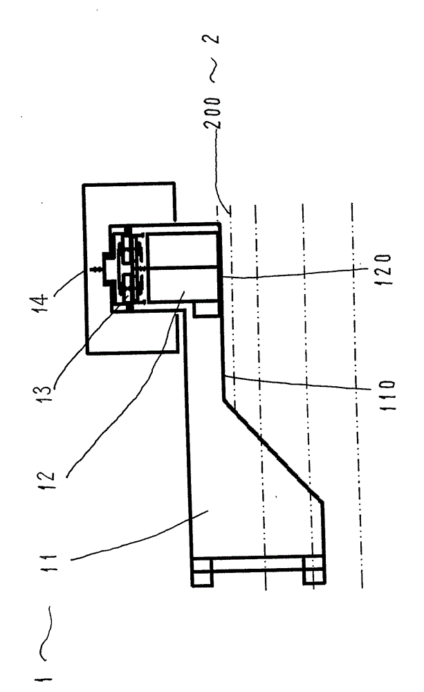
[0003] 1. The first solution of the above patent application - the motor and the roller are coaxial, the output of the motor is connected to a multi-stage planetary gear train, and its axial dimension is as large as Figure 4 As shown, the motor 12' is located above the groove side 2, and the extended end line 120' of the motor 12' protrudes inside the edge line 200 of the groove side 2 near the drum side. When the rocker arm of the cutting device 1' swings, it will Seriously affect its undercover amount, that is, the undercover amount of the shearer at the nose and tail of the transporter is negative, and the bottom plate cannot be 
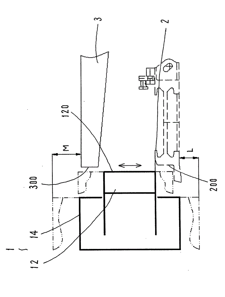
cut through; in addition Figure 5 As shown, the motor 12' is located below the front beam 3 of the bracket, and the outstretched end line 120' of the motor 12' protrudes inside the edge line 300 near the drum side of the front beam 3 of the bracket. When the rocker arm of the cutting device 1' swings, It will seriously affect its top adjustment (when the rocker arm is installed with a small-diameter drum), the above-mentioned factors will make the technical solution of the Chinese patent application publication number CN101812984A unable to meet the mining of thin coal seams or thinner coal seams;
[0004] 2. The second scheme of the above patent application - there are multiple fixed-axis gear trains connected between the motor 12' and the drum 14'. In addition to the problems in the first scheme above, the second scheme has a large change in the thickness of the coal seam on the working face 1. When the angle of the working face is large, the lubrication at both ends of the high and low speeds cannot be properly solved;
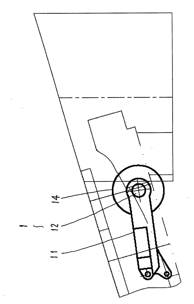
[0005] 3. Regardless of the above-mentioned structure, when the shearer, conveyor, and support (three machines) connected to the multi-stage planetary gear train cutting device are at the nose and tail of the conveyor, if Image 6 As shown, there are triangular coals left on the nose and tail of the machine (the black body of the triangle in the figure), which requires additional manual processing, which is cumbersome to operate and reduces work efficiency

Method used


Image

  • Cutting device of coal cutter
  • Cutting device of coal cutter
  • Cutting device of coal cutter

Examples


Embodiment Construction

[0016] refer to figure 1 , 2 , 3. The shearer cutting device 1 includes a casing 11 , a motor 12 , a planetary gear train 13 and a drum 14 .

[0017] The housing 11 is the main component of the cutting device 1, and each component part of the device is installed on the housing 11. The structure of the housing 11 is basically similar to that of the prior art. Body 11 can be formed into a narrower structural shape.

[0018] The motor 12 has the same structure as the prior art, and the feature of the present invention is that the motor 12 is accommodated in the inner chamber of the drum 14 along the axial direction, such as figure 1 As shown, the extended end wire 120 on the side near the groove side 2 of the motor 12 is flush with the rocker arm side 110 of the housing 11 after the motor 12 is installed, so the outer end wire 120 on the side near the groove side 2 of the motor 12 and There is a gap between the edge line 200 on the side near the cylinder 14 of the groove sid...


PUM


Abstract

The invention relates to a cutting device of a coal cutter, which mainly solves technical problems including both the floor-based quantity and the roof brushing quantity of the coal cutter. Technical schemes adopted in the invention comprise that a motor of the cutting device is in driven connection with a primary planetary gear train with large speed ratio, wherein the planetary gear train is in driven connection with a roller, and the motor is positioned in a cavity of the roller; and that a gap exists between an overhanging end line of the motor and an edge line of a ledge, and a gap exists between the overhanging end line of the motor and an edge line of a support front beam. Thus, the cutting device can better satisfy requirements for the floor-based quantity and the roof brushing quantity when the diameter of the roller is small, and is suitable for exploitation works in thin coal seams or relatively thin coal seams.

Description

Technical field: [0001] The invention relates to a cutting machine, in particular to a cutting rod. Background technique: [0002] Existing drum-type cutting devices of coal shearers widely use motors to be arranged horizontally, and each cutting part is driven by an independent motor. transmission, and then decelerate the drive drum through the planetary gear system to realize its cutting function. With the continuous development of coal mining technology, the power of the shearer cutting device is also increasing. The above transmission mode is not only low in transmission efficiency, but also The cutting device must be cooled by heat radiation, and its structure is also complicated. Therefore, how to improve the mechanical transmission efficiency of the cutting device is particularly important; Device", application publication number CN101812984A, proposes a new solution to the above technical problems, which is characterized in that: the drive motor in the housing of th...

Claims


Application Information

Patent Timeline
Patent Type & Authority Applications(China)
IPC IPC(8): E21C25/10
Inventor 章立强周常飞贠瑞光李辉杰
Owner SHANGHAI TIANDI MINING EQUIP TECH CO LTD
Why Eureka
Try Eureka