Fuel control system of gas turbine

A technology of gas turbine and fuel control, which is applied in the direction of turbine/propulsion fuel delivery system, fuel control of turbine/propulsion device, charging system, etc., and can solve problems such as reduced combustion efficiency and reduced fuel flow

Active Publication Date: 2012-10-24
SHENZHEN WISDOM ENERGY TECH CO
View PDF11 Cites 3 Cited by
  • Summary
  • Abstract
  • Description
  • Claims
  • Application Information

AI Technical Summary

Problems solved by technology

However, as fuel flow through the fuel nozzles decreases, so does their combustion efficiency
At this tim...

Method used


Image

  • Fuel control system of gas turbine
  • Fuel control system of gas turbine
  • Fuel control system of gas turbine

Examples


Embodiment Construction

[0022] Before describing the embodiments in detail, it should be understood that the present invention is not limited to the detailed structures or arrangements of elements described herein below or in the accompanying drawings. The present invention can be implemented in other ways. Also, it should be understood that the phraseology and terminology used herein are for descriptive purposes only and should not be interpreted as limiting. The terms "including", "comprising", "having" and similar expressions used herein are meant to include the items listed thereafter, their equivalents and other additional items. In particular, when "a certain element" is described, the present invention does not limit the number of the element to one, but may also include a plurality.

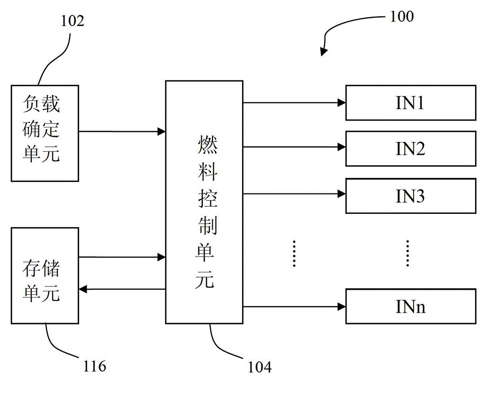
[0023] figure 1 is a schematic diagram of a gas turbine fuel control system. The gas turbine includes a combustor and a plurality of fuel nozzles I N1 , IN2 , IN3 . . . INn communicating with the combustor to...


PUM


Abstract

The invention provides a fuel control system of a gas turbine. The fuel control system mainly comprises a load determining unit and a fuel control unit. The load determining unit is used for determining load information of the gas turbine, and the fuel control unit is used for receiving the determined load information and controlling fuel nozzles of the gas turbine to be opened or closed selectively according to the received load information, so that the sum of rated flow of the opened fuel nozzles is matched with the determined load information. Regardless of a high-load condition or a low-load condition, the flow of each opened fuel nozzle can be lower than the rated flow of the opened fuel nozzle all along during working, so that the combustion efficiency of each fuel nozzle can keep the highest, and a total combustion system keeps the highest combustion efficiency basically.

Description

technical field [0001] The invention relates to a gas turbine, in particular to a fuel control method of the gas turbine. Background technique [0002] The fuel of the gas turbine is generally injected into the combustor through multiple fuel nozzles for combustion. At design time, each fuel nozzle has a set rated flow rate. This set flow is designed for the maximum allowable load of the engine. For these fuel nozzles, only when they operate at their rated flow rate can they achieve the maximum design combustion efficiency and effectively control emissions such as nitrogen oxides or carbon monoxide. However, when the gas turbine is working, there will always be some changing working conditions. In case of variable working conditions, for example, working under partial load, the current common practice is to throttle each fuel nozzle through a proportional valve. After throttling, the flow rate of the fuel nozzles becomes smaller, so that the sum of the fuel flows injecte...

Claims


Application Information

Patent Timeline
IPC IPC(8): F02C9/56
Inventor 王志强
Owner SHENZHEN WISDOM ENERGY TECH CO
Why Eureka
Try Eureka