

All-wind-direction combined multi-power permanent magnetic wind power generator
A permanent magnet generator and multi-power technology, which is applied in the directions of wind power generators, wind power motor combinations, wind power generator components, etc. at right angles to the wind direction, and can solve problems such as the power conversion efficiency of the unit that cannot operate normally
- Summary
- Abstract
- Description
- Claims
- Application Information
AI Technical Summary
Problems solved by technology
Method used
Image

Examples
specific Embodiment approach 1
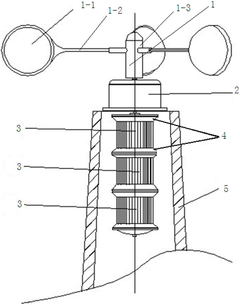
[0012] Specific implementation mode 1. Combination figure 1 Specifically explain this embodiment, the all-wind-direction combined multi-power permanent magnet wind generator described in this embodiment includes a kinetic energy conversion device 1, a radial magnetic coupling reducer 2, a plurality of power permanent magnet generators 3 and a base tower 5,
[0013] The radial magnetic coupling reducer 2 is fixed on the top of the base tower 5. The radial magnetic coupling reducer 2 is a speed-limiting reduction box with a special structure. deceleration mechanism.
[0014] The rotating shaft sleeve 1-3 of the kinetic energy conversion device 1 is sleeved on the torque input shaft of the radial magnetic coupling reducer 2,
[0015] The torque output shaft of the radial magnetic coupling reducer 2 is fixedly connected with the torque input shaft of the power permanent magnet generator 3,
[0016] A plurality of power permanent magnet generators 3 are located inside the base to...
specific Embodiment approach 2
[0021] Specific embodiment two, combine figure 1 Specifically explaining this embodiment, the difference between this method and the all-wind-direction combined multi-power permanent magnet wind generator described in Embodiment 1 is that there are two power combination units permanent magnet generators 3 .
[0022] In this embodiment, the permanent magnet generators 4 of the power combining units can be combined arbitrarily according to the conditions of wind energy resources, so that the permanent magnet generators 4 of the power combining units can be fully utilized.
specific Embodiment approach 3
[0023] Specific embodiment three, combine figure 1 Specifically explaining this embodiment, the difference between this method and the all-wind-direction combined multi-power permanent magnet wind motor described in Embodiment 1 or Embodiment 2 is that it also includes a plurality of combined fastening steel rings 4, and each combined fastening The solid steel ring 4 includes two steel rings, and the two steel rings are respectively located at the two ends of a power permanent magnet generator 3 for fastening the power permanent magnet generator 3, and each combined fastening steel ring 4 All are fixedly connected with the tower wall of base tower 5.
PUM
 Abstract
Description
Claims
Application Information