
Centrifugal pump impeller with low specific speed

A centrifugal pump impeller, low specific speed technology, applied in the field of centrifugal pumps, can solve the problems of easy to appear hump in the lift curve, overload of the supporting motor, shorten the service life of the pump, etc., to reduce the range of vortex and secondary flow, and strengthen the energy conversion ability. , the effect of reducing mechanical loss

Inactive Publication Date: 2012-10-24
SHANGHAI EAST PUMP(GRP) CO LTD
View PDF0 Cites 14 Cited by
  • Summary
  • Abstract
  • Description
  • Claims
  • Application Information

AI Technical Summary

Problems solved by technology

At the same time, this kind of pump has the following problems: the disc friction loss and hydraulic loss are relatively large, the efficiency is generally low, and energy waste is serious; under the condition of small flow rate, the operation is unstable, and the head curve is prone to hump; the shaft power curve increases with the flow rate However, if it rises sharply, it will easily cause the supporting motor to be overloaded when running in a large flow area; the cavitation performance is poor, and it is easy to cause vibration and noise due to cavitation, which shortens the service life of the pump.
Therefore, in the design of traditional impellers, the relationship between the head and the blade outlet placement angle obtained by the above formula is not fully utilized.

Method used


Image

  • Centrifugal pump impeller with low specific speed
  • Centrifugal pump impeller with low specific speed

Examples


Embodiment Construction

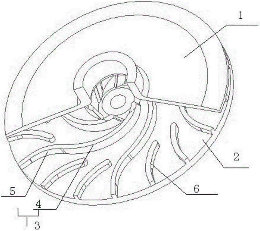
[0016] The preferred embodiments of the present invention are given below in conjunction with the accompanying drawings to describe the technical solution of the present invention in detail. figure 1 It is a schematic diagram of the present invention, such as figure 1 As shown, the present invention includes:

[0017] A low specific speed centrifugal pump impeller, comprising: a front cover 1, a rear cover 2, and a main blade 3, wherein the front cover 1 and the rear cover 2 are disc structures, the front cover 1, the rear cover 2 There are a plurality of main blades 3 evenly distributed in the axial direction, and the main blades 3 are consolidated with the front cover plate 1 and the rear cover plate 2, and the back-curved inlet section 4 is set near the center of the impeller. And the forward curved outlet section 5 is set near the edge of the impeller, the curved direction of the backward curved inlet section 4 is opposite to the direction of rotation of the impeller, and...


PUM


Abstract

The invention relates to a centrifugal pump impeller with a low specific speed. The centrifugal pump impeller comprises a front cover plate, a rear cover plate and main blades, wherein the front cover plate and the rear cover plate are respectively of a circular disc structure; and a plurality of main blades are uniformly distributed between the front cover plate and the rear cover plate along an axial direction and are fixedly connected with the front cover plate and the rear cover plate. The centrifugal pump impeller with the low specific speed is characterized in that rear bent inlet sections are arranged on the parts, close to the center of the impeller, of the main blades; front bent outlet sections are arranged on the parts, close to the edge of the impeller, of the main blades; the bending directions of the rear bent inlet sections are opposite to the rotating direction of the impeller; the bending directions of the front bent outlet sections are opposite to the bending directions of the rear bent inlet sections; the rear bent inlet sections and the front bent outlet sections are smoothly connected with each other; and a plurality of short blades are arranged between each two adjacent front bent outlet sections. The centrifugal pump impeller with the low specific speed is good for overcoming flow releasing and secondary flow in a flow channel, thus reducing the waterpower loss, improving the working efficiency and realizing the aim of saving energy and water.

Description

technical field [0001] The invention belongs to the field of centrifugal pumps, and in particular relates to an impeller of a low specific speed centrifugal pump with less hydraulic loss, high working efficiency, energy saving and water saving. Background technique [0002] The country's "Implementation Opinions on Ten Key Energy Conservation Projects during the Eleventh Five-Year Plan" proposed ten energy-saving projects to achieve the goal of reducing energy consumption per unit of GDP by about 20% during the "Eleventh Five-Year Plan" period. In this "Implementation Opinions", the pump Was included in the "Electric Motor System Energy Conservation Project". Industrial energy conservation is the focus of energy conservation work in the whole society, and it is also an important means for the country to implement macro-control and economic structural adjustment. Equipment energy consumption is a prominent part of industrial energy consumption, and water pump products are on...

Claims


Application Information

Patent Timeline
IPC IPC(8): F04D29/22
Inventor 吴永旭吴志旺
Owner SHANGHAI EAST PUMP(GRP) CO LTD
Learn More