Novel structural high-pressure balance valve

A new type of structure and balance valve technology, applied in the field of balance valves, can solve the problems of increased material cost and machining cutting amount, corrosion resistance, poor high temperature resistance, difficulty in assembly and maintenance of large valves, etc., to achieve superior performance and low friction coefficient , The valve is compact and beautiful

Active Publication Date: 2012-10-24
YUEYANG ZHUSHENG VALVE PIPELINE
View PDF9 Cites 12 Cited by
  • Summary
  • Abstract
  • Description
  • Claims
  • Application Information

AI Technical Summary

Problems solved by technology

[0002] In the current high-pressure balance valve, the stuffing box is pressed tightly by the bracket, and the stuffing box is affected by the high-pressure medium, which generates a large upward axial force. The bracket bears this axial force. At this time, the bracket must have sufficient strength, so the bracket is very Bulky; due to the large load of the fixing bolts of the bracket, the bolt specifications are correspondingly large, so the torque for tightening the nuts is relatively large, which makes the assembly and maintenance of large valves difficult; the valve is sealed with V-shaped packing or stone packing, and the internal parts of the valve move The frictional resistance is relatively large, and it is more cumbersome to assemble the packing. Although some valves are sealed with rubber O-rings, their corrosion resistance and high temperature resistance are poor; The valve, the connecting joint between the valve disc and the valve stem adopts an integral structure connected with the valve disc, so the height of the valve disc is relatively large, and most of the stuffing boxes that contain the valve disc also need to be made larger. This increases the material cost and machining cutting amount of the two, and the structure of the traditional high-pressure balance valve can be seen figure 1

Method used


Image

  • Novel structural high-pressure balance valve
  • Novel structural high-pressure balance valve
  • Novel structural high-pressure balance valve

Examples


Embodiment Construction

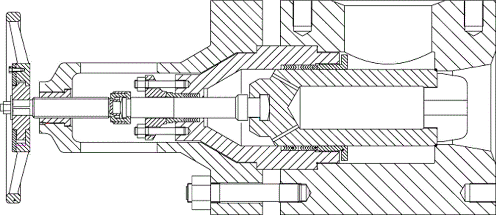
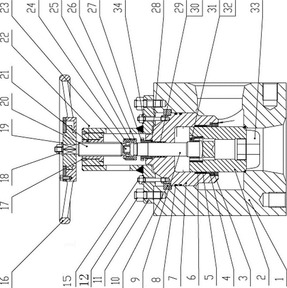
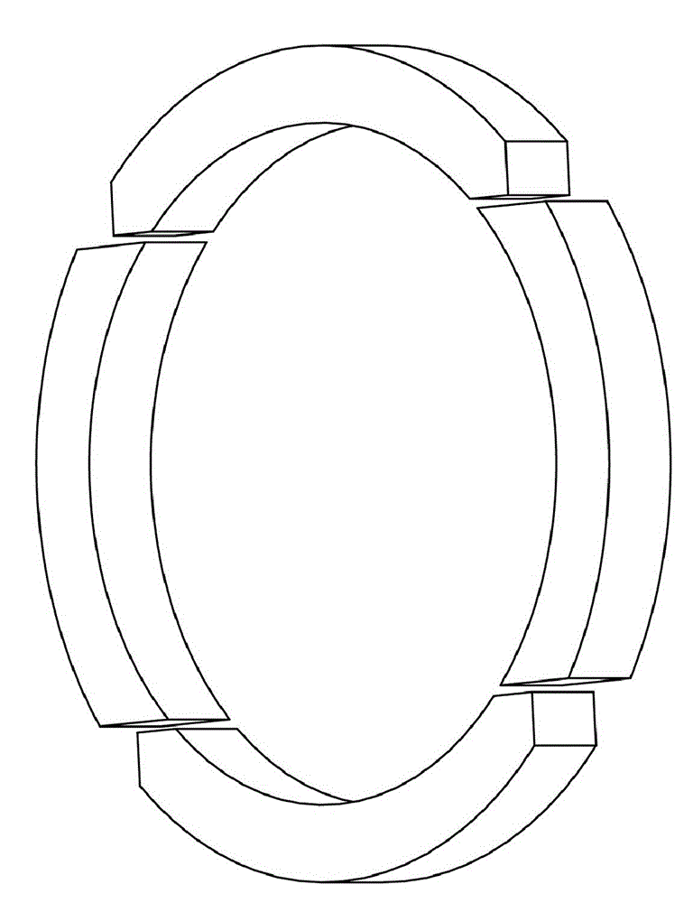
[0026] Depend on Figures 1 to 10 It can be seen that the present invention includes a valve body 1, a stuffing box assembly, a valve stem assembly, a bracket assembly, a handwheel assembly, a four-way ring 10 and a split jacket 26, wherein:

[0027] The inside of the valve body 1 is a cavity, with holes on its upper, lower, and side surfaces. The fluid enters the valve body 1 through the bottom hole of the valve body 1 and flows out through the measuring hole; The assembly seals the high-pressure medium in the valve body 1 and fixes the valve stem assembly; the valve stem assembly is interspersed in the stuffing box assembly, and the valve stem assembly moves up and down to realize the opening and closing of the measuring hole of the valve body 1; the valve body 1 and the stuffing box assembly The upper part of the bracket assembly is provided with a bracket assembly, the bracket assembly is fixed on the valve body 1, and is auxiliary connected to the stuffing box assembly; t...


PUM


Abstract

The invention relates to a novel structural high-pressure balance valve, which comprises a valve body (1), a stuffing box assembly, a valve rod assembly, a support assembly, a hand wheel assembly, a four-element ring (10) and a split jacket (26), wherein a concave groove is arranged on the inner wall of a top hole of the valve body, the four-element ring (10) is arranged on the concave groove, aninner ring of the four-element ring (10) protrudes out of the concave groove, and the bottom of a projection part is in contact with the top surface of the stuffing box assembly; the valve rod assembly comprises a valve rod (9) inserted into the stuffing box assembly and a valve clack (2), the top of the valve rod (9) is connected with the support assembly through the split jacket (26), the valveclack (2) is a cylindrical cavity, a pressing plate is arranged in the valve clack (2), an inner wall of the valve clack (2) at the upper part of the pressing plate is a screw thread, the screw thread is connected with a thread spacer sleeve (31), the bottom of the valve rod (9) is inserted into the thread spacer sleeve (31), the bottom of the valve rod (9) protrudes, the bottom of the thread spacer sleeve (31) is concave, the valve rod (9) and the thread spacer sleeve (31) are matched, so that the valve rod (9) and the thread spacer sleeve (31) are in lapped joint; the stuffing box assembly comprises a stuffing box (7), a first O-shaped sealing part, a second O-shaped sealing part and a third O-shaped sealing part; an O-shaped ring is an F4 type all-coated fluororubber O-shaped sealing ring, and is an axially assembled structure; and fluid balance holes are arranged on the pressing plate in the valve clack (2) and the thread spacer sleeve (31). The novel structural high-pressure balance valve, provided by the invention, has the advantages of simple structure, convenience for use and small volume.

Description

technical field [0001] The invention relates to a balance valve used in petroleum, chemical industry, thermal power and other industries, in particular to a high-pressure balance valve with a new structure. Background technique [0002] In the current high-pressure balance valve, the stuffing box is pressed tightly by the bracket, and the stuffing box is affected by the high-pressure medium, which generates a large upward axial force. The bracket bears this axial force. At this time, the bracket must have sufficient strength, so the bracket is very Bulky; the fixed bolts of the bracket have large loads and correspondingly large bolt specifications, so the torque for tightening the nuts is relatively large, making assembly and maintenance of large valves difficult; the valve is sealed with V-shaped packing or stone packing, and the valve internals move The frictional resistance is relatively large, and the assembly of the packing is more cumbersome. Although some valves are ...

Claims


Application Information

Patent Timeline
Patent Type & Authority Applications(China)
IPC IPC(8): F16K1/00F16K27/02F16K1/48F16K41/02F16K31/60
Inventor 王益民邓筑生
Owner YUEYANG ZHUSHENG VALVE PIPELINE
Why Eureka
Try Eureka