Ash cooling device for garbage burning

A waste incineration ash and cooling device technology, applied in the direction of incinerators, combustion methods, combustion types, etc., can solve the problems of drying heat consumption, high failure rate, and reducing the service life of refractory materials in waste incineration devices, achieving simple structure, The effect of low failure rate

Active Publication Date: 2012-10-24
NANJING KISEN INT ENG
View PDF6 Cites 8 Cited by
  • Summary
  • Abstract
  • Description
  • Claims
  • Application Information

AI Technical Summary

Problems solved by technology

[0005] At present, the ash generated by waste incineration in waste incinerators is cooled by water to cool down. The service life of the material; because it requires a large amount of cooling water and a separate circulating water system, the circulating water is easy to leak, and at the same time, the mechanical system structure of its operation is relatively complicated, and the failure rate is high; in addition, the ash after water cooling contains moisture, When the ash is used later (for example, the ash is used as part of the raw material to grind it into cement raw meal, and then sent to the firing system of the cement production line to be fired into cement raw meal), it needs to consume more drying heat

Method used


Image

  • Ash cooling device for garbage burning
  • Ash cooling device for garbage burning
  • Ash cooling device for garbage burning

Examples


Embodiment 1

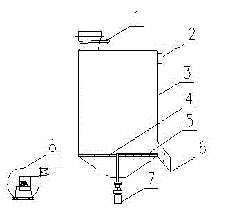
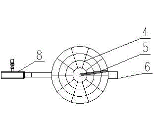
[0028] The specific structure of a waste incineration ash cooling device is as follows: figure 1 , which consists of slag inlet (1), hot air outlet (2), cooling device housing (3), inflatable chassis (4), slag retaining plate (5), slag discharge port (6), transmission motor (7) and Cooling blower fan (8) etc. are formed. The garbage is discharged after being incinerated by the incineration device, and the ash enters the cooling device (3) through the slag inlet (1), and the cooling air is blown into the inflatable chassis (4) of the cooling device by the cooling fan (8), and the cooled ash is blocked The slag plate (5) is scraped into the slag outlet (6) and then discharged from the cooling device. The hot air after the heat exchange between the cold air and the hot ash is discharged from the hot air outlet (2), and then returns to the waste incineration device or the air chamber for waste drying. Dry and incinerate, or use for other purposes. By controlling the rotating spe...

Embodiment 2

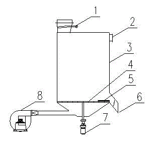
[0031] The specific structure of a waste incineration ash cooling device is as follows: image 3 , which consists of slag inlet (1), hot air outlet (2), cooling device housing (3), inflatable chassis (4), slag retaining plate (5), slag discharge port (6), transmission motor (7) and Cooling blower fan (8) etc. are formed. The garbage is discharged after being incinerated by the incineration device, and the ash enters the cooling device (3) through the slag inlet (1), and the cooling air is blown into the inflatable chassis (4) of the cooling device by the cooling fan (8), and the cooled ash is blocked The slag plate (5) is scraped into the slag outlet (6) and then discharged from the cooling device. The hot air after the heat exchange between the cold air and the hot ash is discharged from the hot air outlet (2), and then returns to the waste incineration device or the air chamber for waste drying. Dry and incinerate, or use for other purposes. By controlling the rotating spe...


PUM


Abstract

The invention discloses an ash cooling device for garbage burning, which comprises parts for controlling ash entering, cooling and ash discharging; according to the ash cooling device, the cooling of ash is realized, and the heat energy of hot ash can be used for heating air so as to dry and burn garbage; and by the adoption of the device, the dry-process cooling and the discharging of ash during garbage burning are realized, harmlessness of ash and reasonable utilization of heat energy during garbage burning are realized, a variety of disadvantages caused by water-cooled deslagging are avoided, and the device is an energy-saving, safe and environment-friendly ash cooling device for garbage burning in the field of garbage treatment.

Description

technical field [0001] The invention belongs to the technical field of garbage disposal, in particular to technology and equipment for cooling ash of garbage incineration. Background technique [0002] Municipal solid waste disposal has increasingly become a worldwide concern, and it is a very arduous comprehensive and systematic project. At present, the more effective treatment method is the incineration method, which is also a garbage treatment method commonly used in countries all over the world. It has the characteristics of large treatment capacity, good capacity reduction and heat recovery. Among them, the layer combustion type garbage incineration device has the characteristics of not needing to sort garbage and being suitable for garbage with high moisture content and low calorific value in my country. From the perspective of thoroughness, harmlessness and environmental protection of waste disposal, it is more appropriate for cement production line to co-dispose was...

Claims


Application Information

Patent Timeline
Patent Type & Authority Applications(China)
IPC IPC(8): F23G5/44F23J1/06F23G5/46
Inventor 陈艳征康宇祁亚军冯治国李安平
Owner NANJING KISEN INT ENG
Why Eureka
Try Eureka