Two-phase flow power heat pipe device

A heat pipe device and fluid power technology, applied in the field of heat exchange, can solve the problems of incomplete gas-liquid separation, insufficient circulation power, etc., and achieve the effect of solving the problems of high and low position difference and conveying distance, reducing the limitation of use conditions and having a simple structure

Active Publication Date: 2012-10-24
BEIJING FULLLINK OREITH TECH CO LTD
View PDF5 Cites 16 Cited by
  • Summary
  • Abstract
  • Description
  • Claims
  • Application Information

AI Technical Summary

Problems solved by technology

[0006] A new type of heat pipe heat exchange device technology provided by the present invention—a two-phase flow power heat pipe device is to solve the problems of incomplete gas-liquid separation and insufficient circulation power existing in the current power heat pipe work

Method used


Image

  • Two-phase flow power heat pipe device
  • Two-phase flow power heat pipe device
  • Two-phase flow power heat pipe device

Examples


specific Embodiment approach 2

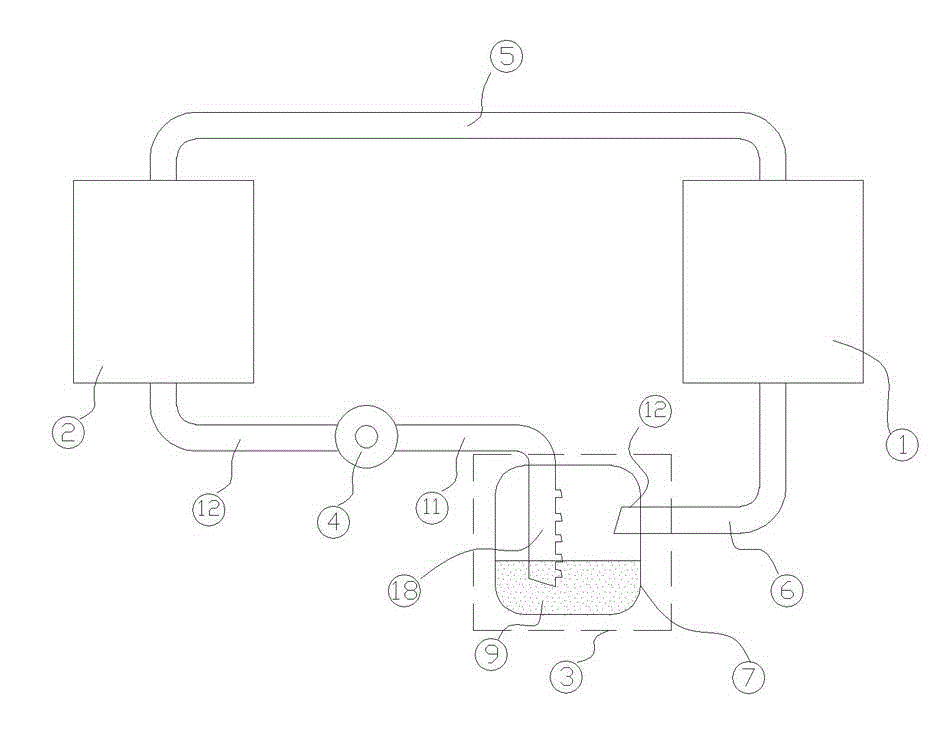
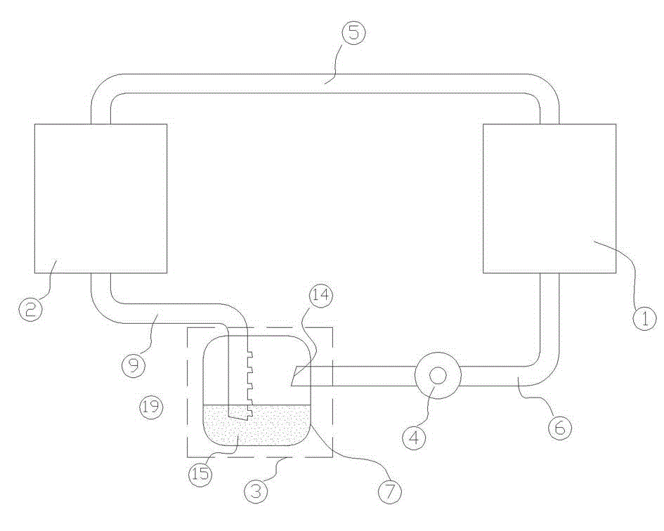
[0030] figure 2 A schematic structural diagram of the second embodiment of the system is given, in figure 1 On the basis of the above, the liquid storage and distribution device (3) is connected between the evaporator (2) and the circulation pump (4), which includes the liquid storage tank (7), the evaporator input port (15), the return hole two (19 ) and the circulation pump output end (14); the evaporator input end (15) is located at the lower part of the liquid refrigerant liquid level in the liquid storage tank (7), and the circulation pump output end (14) is located at the liquid storage tank ( 7) The upper part of the internal liquid refrigerant liquid level; the evaporator (2), condenser (1), circulation pump (4) and liquid storage and distribution device (3) are connected into a single unit through interconnecting pipes in the above order Two-phase flow dynamic heat pipe device to the circulation. The circuit control element controls the opening and running state of...

specific Embodiment approach 3

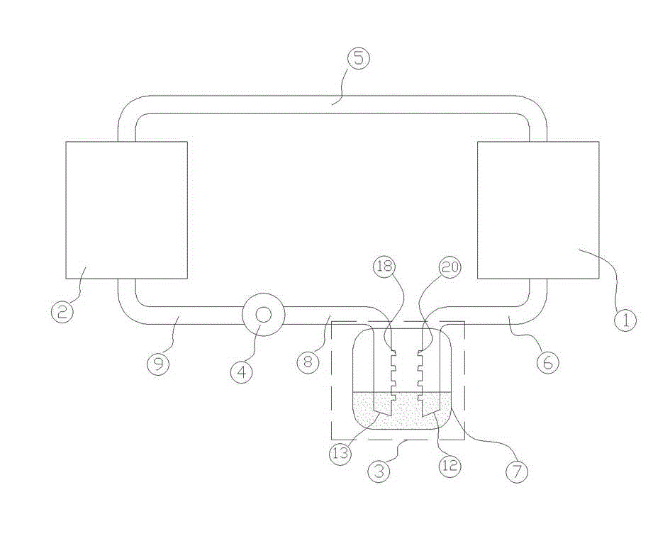
[0032] In a specific environment, in order to exchange the functions of the condenser (1) and the evaporator (2) in the system, that is, the condenser (1) acts as an evaporator, and the evaporator (2) acts as a condenser, Improvements are made on the basis of the first embodiment.

[0033] The circulation pump (4) is changed from a one-way circulation pump to a two-way power motor system (such as Roots motor) that can directly change the direction, and the part where the condenser liquid conduit (6) is located in the liquid storage and diversion device (3) and the circulation pump The design of the part of the suction pipe (8) inside the liquid storage and distribution device (3) is the same, and the simple structure diagram of this embodiment is shown in image 3 shown.

[0034] In this system, when the condenser (1) and the evaporator (2) function normally, the specific work implementation mode is the same as the specific implementation mode 1. When the condenser (1) plays ...


PUM


Abstract

The invention discloses a two-phase flow power heat pipe device. The two-phase flow power heat pipe device is mainly composed of a condenser, a storage liquid shunting device, a circulating pump, an evaporator and a circuit control element, wherein the storage liquid shunting device is composed of a liquid storage tank, input and output ends of a liquid draining pipe and a backflow hole, thus the collection, complete separation and shunt of two-phase flow can be realized, and a whole system can have stable gas-liquid two-phase flow circulation; the backflow hole is provided with a liquid backflow hole and a gas backflow hole, the gas backflow hole is positioned above the liquid level in the liquid storage tank, and the liquid backflow hole is positioned under the liquid level in the liquid storage tank; the condenser and the evaporator are used for realizing the transportation of energy; the circulating pump is connected between a liquid inlet end of the evaporator and a liquid outlet end of the condenser; and the circuit control element controls the running state of the system. The two-phase flow power heat pipe device disclosed by the invention has the advantages that through the design of the storage liquid shunting device and the circulating pump, the problems of incomplete gas-liquid separation and insufficient circulation power in a heat pipe heat exchange device are solved, the working efficiency and the practicability of the heat pipe are increased, and the whole system device has a simple structure and is environment-friendlly.

Description

technical field [0001] The invention relates to the technical field of heat exchange, in particular to a novel heat pipe heat exchange system, in particular to a split-type two-phase flow heat pipe device with a circulating pump. Background technique [0002] As a high-efficiency heat transfer element, heat pipes are increasingly used in engineering. Heat pipes are not only widely used in waste heat recovery, cooling of electronic components, etc., but also in the field of traditional heat and mass transfer equipment, heat pipes have a tendency to replace circulating water, circulating oil and steam for heat transfer. When the ambient temperature is low, the heat pipe can also replace the current air-conditioning system as a cooling and temperature control element for electronic equipment, power equipment, computer rooms, and communication rooms. [0003] Heat pipes have a variety of structural forms, and there are also a variety of classification methods. Classified accor...

Claims


Application Information

Patent Timeline
Patent Type & Authority Applications(China)
IPC IPC(8): F28D15/02
CPCF28D15/0266
Inventor 祝长宇丁式平
Owner BEIJING FULLLINK OREITH TECH CO LTD
Why Eureka
Try Eureka