Assembled-type probe fixing device and method

A technology of fixing device and fixing method, applied in the direction of measuring device, thermometer parts, instruments, etc., can solve the position deviation of the temperature probe metal bracket and the probe, the temperature probe close to the glass bottle and the probe position deviation, the car can not Use and other problems to achieve the effect of effectively and quickly fixing the probe, fast and convenient connection, and easy and convenient disassembly and assembly.

Inactive Publication Date: 2014-04-30
CHENGDU OLYMVAX BIOPHARM
View PDF4 Cites 0 Cited by
  • Summary
  • Abstract
  • Description
  • Claims
  • Application Information

AI Technical Summary

Problems solved by technology

[0005] Probe layout technology for moist heat sterilizers and dry heat sterilizers: when conducting heat distribution tests with no load, place the probes on an empty car for winding. On the one hand, this arrangement will force the probes to be changed. The probe is broken; on the other hand, the temperature probe will be close to the metal bracket of the empty car and the position of the probe will be offset, and the temperature in the cavity cannot be accurately measured
When the heat distribution test is carried out at full load, due to the different device technology, for example, the load has a moving tank, the car cannot be used, and the temperature value in the cavity cannot be measured only by placing the probe on the load.
When conducting the heat penetration test, for the moving tank cavity, three probes are inserted into the tank hole and placed on the upper, middle and lower sides of the vertical line of the cavity. This probe placement method cannot prove that the temperature of all parts inside the cavity reaches Require
[0006] Tunnel oven probe layout technology: when conducting heat distribution test with no load, the probe is fixed on the moving chain with iron wire. On the one hand, this arrangement will force the probe to change, and long-term use will cause the probe to break; on the other hand, the temperature probe There will be deviation in the position close to the tunnel oven track and the probe, and the temperature in the cavity cannot be accurately measured
When testing the heat distribution at full load, the probe is fixed on the bottle mouth with an iron wire and the probe is turned up. On the one hand, this arrangement will force the probe to change, and it will cause the probe to break after long-term use; on the other hand, the temperature probe will appear tight. The temperature in the chamber cannot be accurately measured due to the offset of the position of the glass bottle and the probe
During the heat penetration test, the probe is fixed on the mouth of the bottle or the moving chain with an iron wire and the probe is inserted into the glass bottle at the same time. On the one hand, this arrangement will force the probe to change, and it will cause the probe to break when used for a long time; on the other hand On the one hand, the temperature probe will not rely on the glass bottle wall and the position of the probe will shift, and the temperature of the glass bottle wall cannot be accurately measured.
[0007] Tank probe layout technology: heat distribution test is carried out during online sterilization. Three probes are inserted into the tank hole and placed on the upper, middle and lower sides of the vertical line of the cavity. This probe placement method cannot prove that the temperature of all parts inside the cavity reaches Require
When testing the heat distribution at full load, insert 3 probes into the tank hole and place them at the top, middle and bottom of the vertical line of the cavity, and higher than the stirring paddle. This probe placement method cannot prove that the temperature values ​​of all parts inside the cavity meet the requirements. At the same time, the temperature probe will be wound on the stirring paddle, and the probe will break

Method used


Image

  • Assembled-type probe fixing device and method
  • Assembled-type probe fixing device and method
  • Assembled-type probe fixing device and method

Examples


Embodiment Construction

[0032] The present invention will be further described below in conjunction with accompanying drawing:

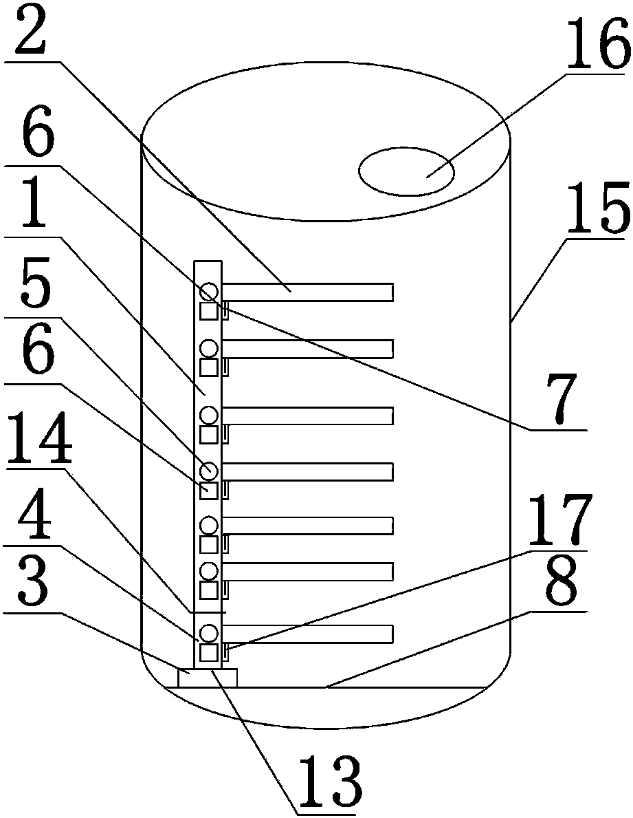
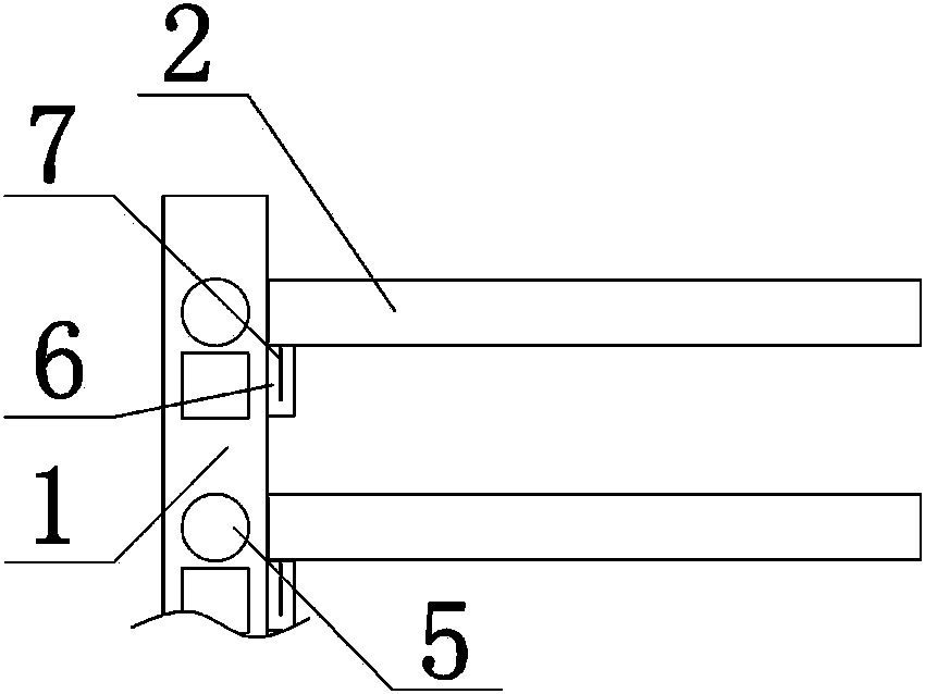
[0033] like figure 1 As shown, the assembled probe fixing device includes a fixed module, a mobile bracket 1 and a movable sleeve 2, the fixed module is composed of a fixed base 3 and a tubular fixed bracket 4, and the fixed bracket 4 is fixed on the top of the fixed base 3 , the top of the fixed bracket 4 is provided with a tubular mobile bracket 1, such as image 3 As shown, there are through holes A5 distributed on the tube wall of the mobile bracket 1, the side of the mobile bracket 1 is also provided with a card slot A6, the side of the mobile bracket 1 is installed with a mobile sleeve 2, and the outer wall of the mobile sleeve 2 is provided with an insert 7. The insert piece 7 is installed in the card slot A6.

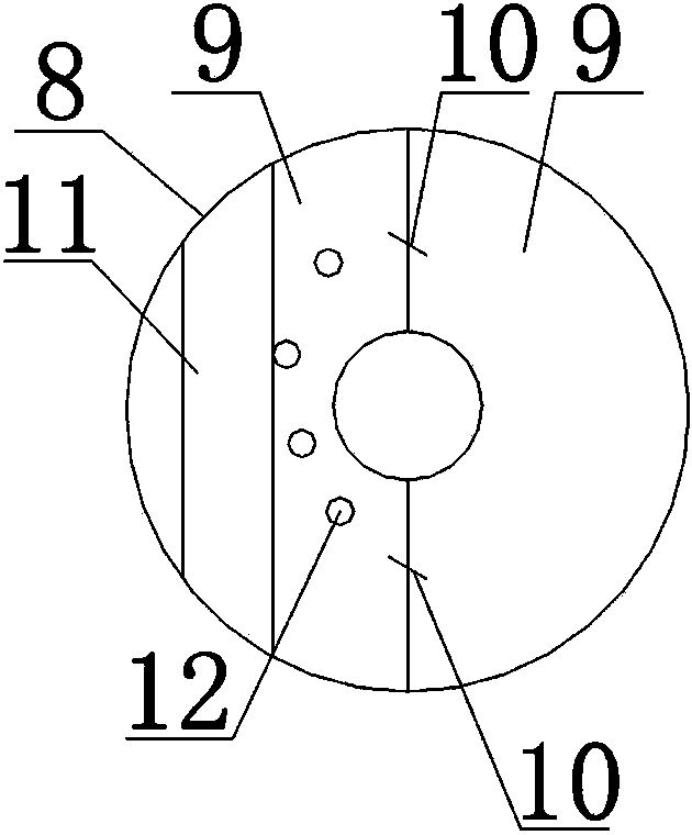
[0034] It also includes a fixed disc 8, such as figure 2 As shown, the fixed disc 8 is composed of two moon-shaped semi-discs 9, and the two moon-shaped ...


PUM


Abstract

The invention discloses an assembled-type probe fixing device, which comprises a fixed module, a movable support (1) and movable casings (2). The fixed module consists of a fixed base (3) and a tubular fixed support (4). The tubular movable support (1) is arranged above the fixed support (4). Through holes A (5) are distributed on the tube wall of the movable support (1). The movable casings (2) are additionally installed on the side surface of the movable support (1). The invention additionally discloses an assembled-type probe fixing method. The assembled-type probe fixing device and the assembled-type probe fixing method have the advantages that the components of the fixing device are simple, the connection is rapid and convenient to conduct, the universality is high, the adjustment flexibility is high, the defects that the probe is apt to be broken and the measuring accuracy is not high in the prior art are overcome, the placing position of the temperature probe is more flexible, the internal temperature of a chamber can be accurately measured, the application scope is wide, the operation process for arranging the probe is simple and the time is greatly saved.

Description

technical field [0001] The invention relates to the technical field of fixing probes in sterilization equipment, in particular to an assembled probe fixing device and a fixing method thereof. Background technique [0002] Good Manufacturing Practice for Drugs (Revised in 2010) Appendix 1: When thermal sterilization (including moist heat sterilization and dry heat sterilization) is required in Chapter 11 "Sterilization Process" and Chapter 12 "Sterilization Methods" heat sterilization), physical detection means must be used to verify that it has achieved the sterilization effect on all parts of the product or article. Among them, the temperature of thermal sterilization is one of the key physical indicators. [0003] The verification objects include moist heat sterilizers, dry heat sterilizers, tunnel ovens and tanks, etc.; the verification status includes no-load heat distribution, full-load heat distribution and heat penetration test. The strategy used in the actual verif...

Claims


Application Information

Patent Timeline
Patent Type & Authority Patents(China)
IPC IPC(8): G01K1/14
Inventor 李建霖陈克平
Owner CHENGDU OLYMVAX BIOPHARM
Why Eureka
Try Eureka