Combined calibration device of no-coupling six-dimensional force sensor
A six-dimensional force sensor and calibration device technology, applied in the field of sensor calibration, can solve the problems of difficult assembly and debugging, large size, etc., and achieve the effect of simple installation and debugging, small size and high precision
- Summary
- Abstract
- Description
- Claims
- Application Information
AI Technical Summary
Problems solved by technology
Method used
Image

Examples
specific Embodiment approach 1
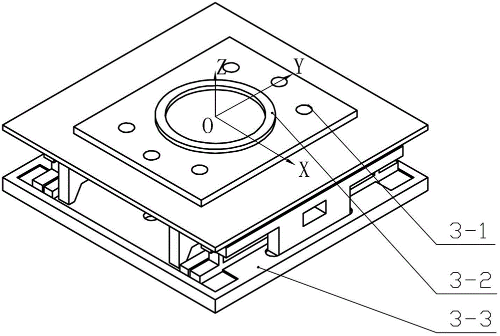
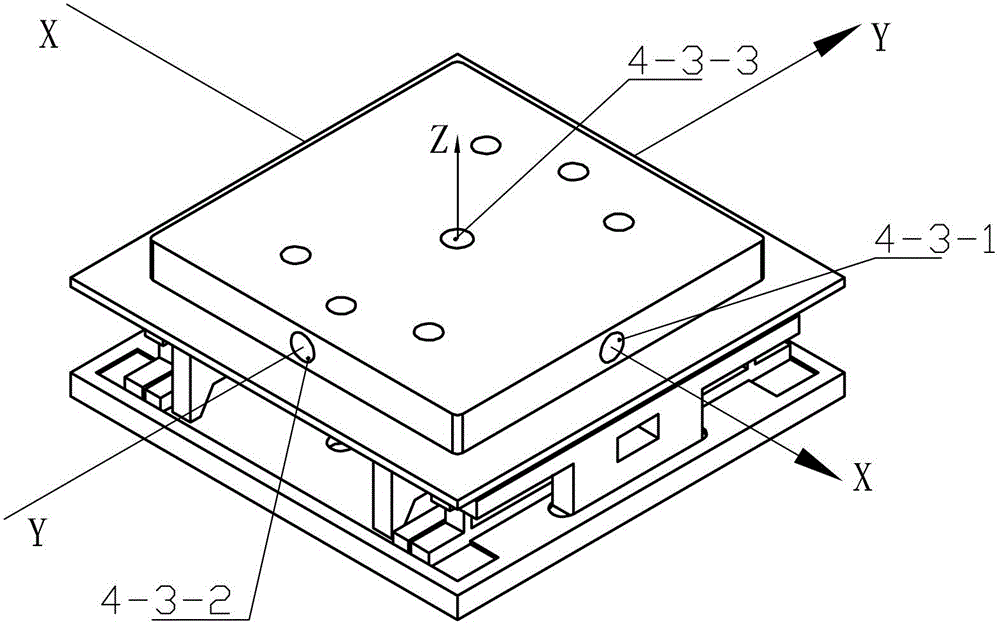
[0023] Specific embodiment one: As shown in Figures 1 to 9, a combined calibration device for an uncoupled six-dimensional force sensor described in this embodiment includes a Fz direction calibration device I; a Fx, Fy direction calibration device II; a Mz direction calibration device Device III; Mx, My direction calibration device IV;
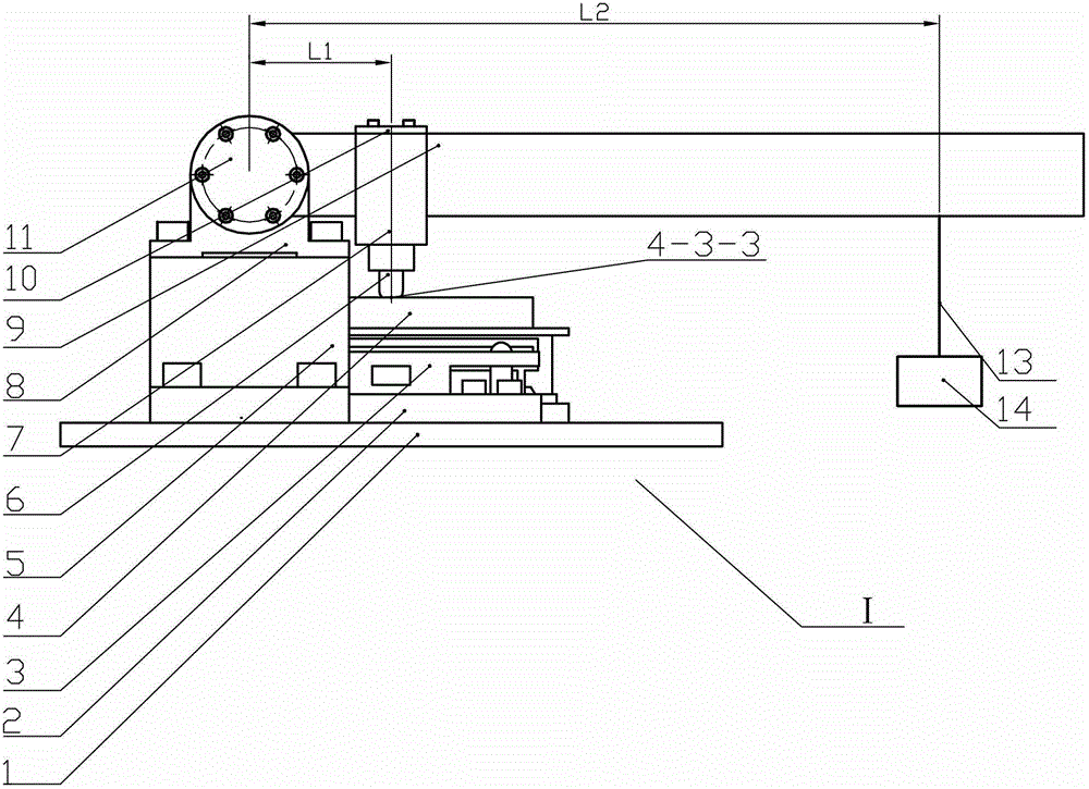
[0024]As shown in Figure 2, the Fz direction calibration device 1 includes a base plate 1, a bead 2, a force transfer plate 4, a support base 5, a loading rod 6, a lower pressure plate 7, a bearing seat 8, a lever 9, an upper pressure plate 10, and a bearing end cover 11. Steel wire rope 13, French code 14 and mandrel 15; support seat 1 is fixed on the upper end surface of base plate 1; 17-1, bearing two 17-2 are installed on the corresponding bearing housing 8, bearing one 17-1, bearing two 17-2 are provided with bearing end cover 11 respectively, lever 9 and mandrel 15 are arranged vertically, lever 9 One end is installed on the mandrel 15...
specific Embodiment approach 2
[0028] Specific implementation mode two: as Figure 7 As shown, the loading pulley assembly 23 in this embodiment includes a retaining ring 23-1, a pulley shaft 23-2, a bearing 3 23-3-1, a bearing 4 23-3-2, a pulley seat 23-4, and a pulley One 23-5 and gasket 23-6; the pulley seat 23-4 is installed on the loading bar one 22, and one end of the pulley shaft one 23-2 is installed through bearing three 23-3-1 and bearing four 23-3-2 In the pulley seat 23-4, the pulley one 23-5 is installed on the other end of the pulley shaft one 23-2, and the pulley one 23-5 is installed on the pulley shaft one 23-2 through the gasket 23-6 and the screw 23-7 ; Other compositions and connections are the same as those in Embodiment 1. Pulley one 23-5 relies on gasket 23-6 and pulley shaft one 23-2 shoulder to realize axial positioning, and gasket 23-6 uses screw 23-7 to be connected with pulley shaft one 23-2. Pulley shaft one is fixed in the pulley seat 23-4 by two bearings 23-3-1, 23-3-. The ...
specific Embodiment approach 3
[0029] Specific implementation mode three: as Figure 8 As shown, the guide pulley assembly 25 in this embodiment includes pulley two 25-1, retaining ring two 25-2, bearing five 25-3-1, bearing six 25-3-2 and pulley shaft two 25-4; Wheel shaft two 25-4 is installed on the column 24, pulley two 25-1 is installed on the pulley shaft two 25-4 through bearing five 25-3-1 and bearing six 25-3-2, and retaining ring two 25-2 is used for Fix the bearing five 25-3-1 positioned at the outer end. Other components and connections are the same as those in the second embodiment. Pulley 2 25-1 is fixed on the pulley shaft 2 25-4 through two bearings 25-3-1 and 25-3-2, and the bearing is axially fixed through the shaft shoulder and retaining ring 25-2. The outer ring of the bearing and the pulley Two 25-4 use interference fit to prevent bearing movement.
PUM
 Abstract
Description
Claims
Application Information
 - R&D
- Intellectual Property
- Life Sciences
- Materials
- Tech Scout
- Unparalleled Data Quality
- Higher Quality Content
- 60% Fewer Hallucinations
Browse by: Latest US Patents, China's latest patents, Technical Efficacy Thesaurus, Application Domain, Technology Topic, Popular Technical Reports.
© 2025 PatSnap. All rights reserved.Legal|Privacy policy|Modern Slavery Act Transparency Statement|Sitemap|About US| Contact US: help@patsnap.com