Method and device for fatigue test crack diagnosis of engine body

An engine body and fatigue test technology, applied in the field of test diagnosis, can solve problems such as errors in fatigue limit values, affecting the company's judgment on the reliability of the engine body, and inaccurate fatigue life results of the engine body, so as to achieve the effect of improving precision and accuracy

Active Publication Date: 2012-10-24
WEICHAI POWER CO LTD
View PDF4 Cites 6 Cited by
  • Summary
  • Abstract
  • Description
  • Claims
  • Application Information

AI Technical Summary

Problems solved by technology

In the actual test, it is necessary to have a special person on duty to watch, and it is necessary to observe whether there is a crack every hour, so that the labor cost in the fatigue test of the body is increased; The actual record of the fatig

Method used


Image

  • Method and device for fatigue test crack diagnosis of engine body
  • Method and device for fatigue test crack diagnosis of engine body
  • Method and device for fatigue test crack diagnosis of engine body

Examples


Embodiment 1

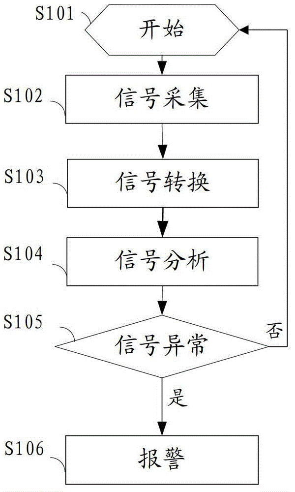
[0040] see figure 1 , which is a flow chart of a method for diagnosing cracks in an engine body fatigue test of the present invention, the method comprising the following steps:

[0041] S101: Start engine body fatigue test.

[0042] S102: the strain gauge and the acceleration sensor respectively collect strain signals and vibration signals of the engine body in the fatigue test.

[0043] S103: The data acquisition card converts the strain signal and the vibration signal into digital signals respectively, and sends the strain signal and the vibration signal converted into digital signals to the industrial computer.

[0044] S104: The industrial computer collects multiple discrete signals from the strain signals and vibration signals converted into digital signals, performs wavelet analysis on the multiple discrete strain signals collected, monitors the signal singularity of the analysis results, and analyzes the collected multiple discrete The vibration signal is subjected t...

Embodiment 2

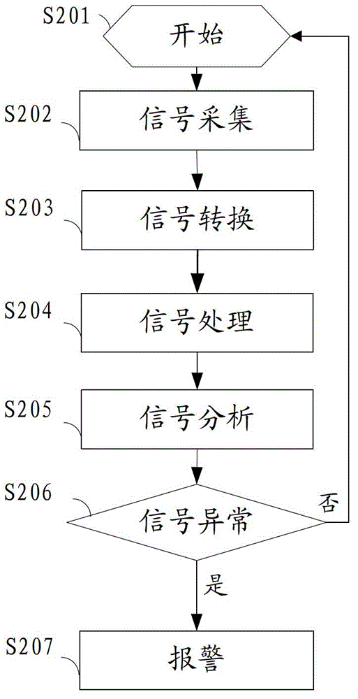
[0053] see figure 2 , which is another flowchart of a method for diagnosing cracks in an engine block fatigue test of the present invention, the method also includes the following steps:

[0054] S201: Start the engine block fatigue test.

[0055] S202: The strain gauge and the acceleration sensor respectively collect strain signals and vibration signals of the engine body in the fatigue test.

[0056] S203: The data acquisition card converts the strain signal and the vibration signal into digital signals respectively, and sends the strain signal and the vibration signal converted into digital signals to the industrial computer.

[0057] S204: The industrial computer performs pasteurized low-pass filtering processing on the strain signal converted into a digital signal, and performs wavelet denoising processing on the vibration signal converted into a digital signal to remove false components.

[0058] What needs to be further explained in step S204 is that the preferred wa...

Embodiment 3

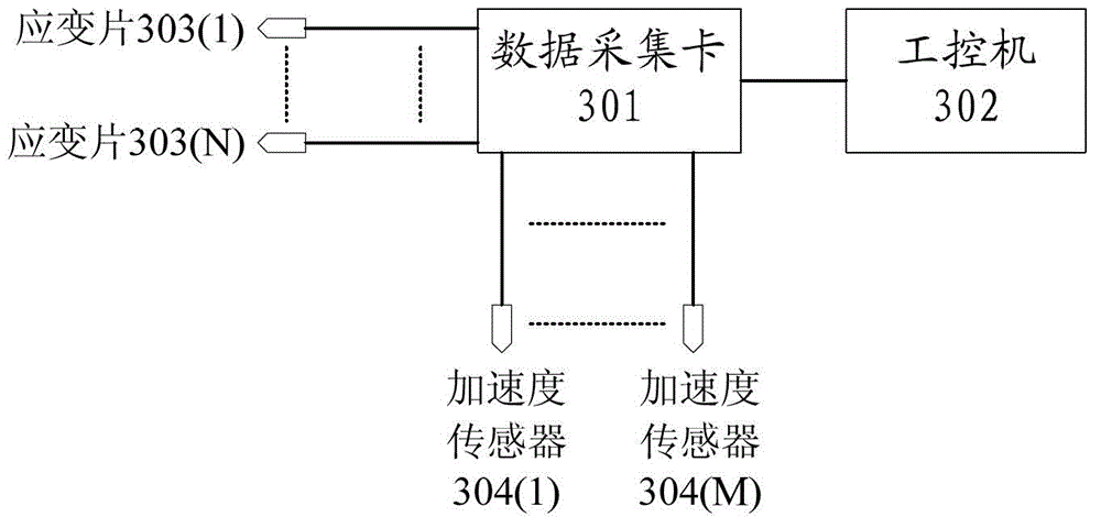
[0066] see image 3 , which is a system structure diagram of an engine body fatigue test crack diagnosis device of the present invention, including a data acquisition card 301, an industrial computer 302, strain gauges 303(1) to 303(N) and an acceleration sensor 304(1) To the acceleration sensor 304 (M), wherein N and M are integers greater than or equal to 1,

[0067] The strain gauges 303(1)-303(N) are used to collect the strain signal of the engine in the fatigue test;

[0068] The acceleration sensors 304(1)-304(M) are used to collect vibration signals of the engine in the fatigue test;

[0069] The data acquisition card 301 is connected to the strain gauges 303(1)-303(N) and the acceleration sensors 304(1)-304(M), and is used to convert the strain signals and vibration signals into digital signals respectively, and sending the strain signal and vibration signal converted into digital signals to the industrial computer.

[0070] The industrial computer 302 is connected ...


PUM


Abstract

An embodiment of the invention discloses a method and a device for fatigue test crack diagnosis of an engine body. A strain foil and an acceleration transducer respectively collect strain signals and vibration signals of the engine body in a fatigue test. A data collection card converts the strain signals and the vibration signals respectively into digital signals and transmits the strain signals and the vibration signals which are converted into the digital signals to an industrial personal machine. The industrial personal machine collects a plurality of discrete signals from the strain signals and the vibration signals which are converted into the digital signals, conducts wavelet analysis on the plurality of collected strain signals, conducts signal singularity monitoring on analysis results, conducts Fourier transform on the plurality of collected discrete vibration signals and conducts characteristic value analysis on conversion results. The industrial personal machine judges whether results of singularity monitoring and characteristic value analysis are abnormal or not and judges that an engine has fatigue cracks on yes judgment. The method and the device can reduce unnecessary manpower and financial resources.

Description

technical field [0001] The invention relates to the field of test diagnosis, in particular to a method and device for diagnosing a fatigue test crack of an engine body. Background technique [0002] For the engine, fatigue refers to the process of forming cracks or breaking after a certain number of cycles due to local permanent structural changes at certain points or points under the action of cyclic stress or cyclic strain. [0003] In the existing engine body fatigue tests, the diagnosis of fatigue cracks in the engine body is generally observed manually with the naked eye. When fatigue cracks are found, sometimes the cracks have expanded to a large size, resulting in very inaccurate test data; and if the cracks are not found in time, it may cause test accidents. [0004] In the existing body fatigue test, there is no special method for diagnosing the fatigue cracks of the body to realize the automatic shutdown of the machine. In the actual test, it is necessary to have...

Claims


Application Information

Patent Timeline
IPC IPC(8): G01N33/00
Inventor 张成强李建锋刘海军陈占善李正现
Owner WEICHAI POWER CO LTD
Why Eureka
Try Eureka